Category Archives: Radio history

Merry Christmas Hans: 1939

Dec1939BL

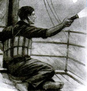
The December 1939 issue of Boys’ Life magazine carries an interesting short story, “Merry Christmas Hans” by Philip Lightfoot Scruggs. It’s full of technical inaccuracies, the author’s unfamiliarity with Amateur Radio, and even countless FCC rule violations. But it’s an interesting look at how Amateur Radio was viewed 75 years ago, and it pretty conclusively puts to rest the assertion that the Boy Scouts are somehow designed to militarize boys.

The hero of the story is Dave Smith, W2KSM. (It looks like the call was really in use, as shown by what looks like a Sweepstakes entry in this 1938 QST. And it was held in 1954 by one Howard M. Ames Jr.)

Young W2KSM, a 17-year-old Eagle Scout, decided to get on the air on Christmas Eve to wish a Merry Christmas to his DX friends in France, England, Belgium, or Holland. Much to his surprise, he heard the voice of Hans Schuler in Germany, where Amateur Radio was not allowed. (Amateur Radio actually did exist in Germany, and even continued somewhat during the war. Germany was one of the few belligerent countries where there were still a few hams on the air, even during the war. For more information, see my earlier post.) The story contains an editor’s note pointing out that the story was written before war was declared. Dave asked Hans what would happen if he was caught, and Hans replied, “the concentration camp at least.”

Still, the two continue their conversation, as Dave tells of freedom, and Hans tells of the repression in Germany, and even explains how he can quickly dismantle the station and antenna if the Gestapo got too close. Another Scout in New York City just happens to be listening to the contact, and alerts his father, a network executive, who spontaneously decides to broadcast the contact nationwide where millions, including Dave’s parents, listen to the boys talk.

Dave tells about Boy Scouts, and Hans tells of his experience preparing for war in the Hitler Youth. Dave concludes the contact by reciting the Scout Oath and Law, “that is our Scout Oath and Law, Hans–what we try to live by,” as Hans prepares to hastily disassemble his clandestine set.

Dave walks downstairs wondering whether his family will believe it, only to hear the end of the broadcast in which he and Hans had a starring role.


Click Here For Today’s Ripley’s Believe It Or Not Cartoon


Minneapolis School A-V Equipment of the 1960’s and 1970’s

SetchellCarlsonTV

If you went to school in Minneapolis in the 1970’s, I bet these pictures look vaguely familiar. This is a 1972 ad from Setchell-Carlson, then known as SC Electronics, Inc., a subsidiary of Audiotronics Corporation, with an address of 530 5th Avenue NW, New Brighton, MN. This ad appears in the March 1972 issue of Broadcast Engineering.

The Minneapolis Public Schools were equipped with what I believe was the model at the left.  I’m showing the one on the right to show the distinctive controls in the center, which are hidden behind the optional “tamper-proof control compartment door” of the black and white model on the left.  I don’t think that Minneapolis had the door, or else the doors were routinely left open.

At Waite Park Elementary School, I don’t believe that every classroom was equipped with a TV.  There were one or two of these that were wheeled in as needed.

AV750Every room, as far as I can recall, was equipped with a radio, although it was rarely used.  The radio, shown here, was the Newcomb Model AV-750.  This was an 8-tube AM FM receiver, and was obviously built for severe service.   I’m sure I’m the only kid who noticed, but it had a connection on the back for an external AM antenna and ground.  I was always jealous of that radio, since I dreamed of all the exotic broadcast band stations it would pull in if connected to an external antenna.  There was also a connection on back for audio input, so it could be used as an audio amplifier.

I’m not positive, but I believe this Audiotronics phonograph was the standard issue model in the Minneapolis schools.  Again, I believe one was issued to each classroom, and they saw a bit more use than the radio.

The televisions were made not far from the school.  Setchell-Carlson made some consumer radios in the 1940’s, and TV‘s in the 1950’s and 1960’s.  They were never a big name nationally, although they did have a strong presence in their home state of Minnesota.  By the 1970’s, they had abandoned the consumer market, but they continued to make the institutional models shown above.

There’s a good history of the company in the October 2008 issue of Radio Age.

bc1206

Photo courtesy of Ian O’Toole, VK2ZIO, Kurrajong Radio Museum. Used by permission.

The company was founded in St. Paul in 1928 by Bart Setchell and Carl Donald Carlson as “Karadio Corporation.” As the name suggests, the company manufactured auto radios. Setchell claimed later to have been the “first” to use vibrators to power the car radio. The author of this article disputes that claim, but it is clear that Setchell-Carlson was one of the pioneers. In 1934, the company became Setchell Carlson, Inc., and made a few radios before the war. During World War II, the company was a defense contractor, and made products for the military, the most famous of which was the aviation receiver shown here. (For more information on this device, see my earlier post.)

In 1949, the company moved to New Brighton,

A Setchell Carlson TV from 1954, back when people apparently dressed up to watch TV. Popular Mechanics, Dec. 1954

A Setchell Carlson TV from 1954, back when people apparently dressed up to watch TV. Popular Mechanics, Dec. 1954

Minnesota, and went into the TV business, which lasted until the 1960’s. At its peak, the company employed about 500, and also had a plant in Arden Hills.  Setchell was later inducted into the Minnesota Broadcasting Hall of Fame.

One final note on the audio-visual equipment in use at my elementary school.  The Minnesota Historical Society has this photo  of the school’s public address system.  The photo is dated about 1955, but based upon the one or two times I saw it, this is the same console that was in use in the 1960’s and 1970’s when I was a student there.  Interestingly, the caption of this photo bills it as a “school broadcasting lab” and shows students at the mike.  I never recall the console being used by students, certainly not on a routine basis.

The couple of times I saw this, I was quite impressed.  It was in a separate room off the office, and in addition to the PA console, there was a radio receiver.  I remember one dial being for the standard AM band.  The other dial was calibrated in some numbers that did not look at all familiar to me.  In retrospect, it’s possible that they were FM channel numbers, which were used for a short time on some FM receivers.
Click Here For Today’s Ripley’s Believe It Or Not Cartoon



Beaver Baby Grand Crystal Set, 1924

BeaverBabyGrandCrystalSet

Presumably, by 1924, most readers of Popular Radio magazine already owned a radio receiver, and judging from the articles and ads in the December 1924 issue, most of those readers already owned a set with one or more tubes.

This probably presented a marketing challenge for the Beaver Machine & Tool Co. of Newark, N.J., maker of, among other things, crystal sets. Since it was the Christmas season, the crystal set was promoted as a gift item. The company advertised its “Baby Grand” crystal set as a way to “spread X’mas joy by giving these efficient little sets to friends less fortunate than yourself.” The ad assured that the set was “not a junky toy, but a handsomely built instrument” that was ideal for invalids or youngsters. It reported that the set would give satisfactory reception up to 25 miles.

The set was available in a handsome gift box, with headphones, for $6. The set by itself, without headphones, sold for $3.40.

From the number of surviving examples, it appears that the radio indeed not a junky toy. Quite a few specimens can be found through a Google Images search.

The Beaver Machine & Tool Co. does not appear to survive today. Its address is what appears to be a residential section of Newark, and there’s no record of the company. At the time of this ad, however, it was involved in a patent infrignement suit regarding electrical switches. It had been sued by Cutler Hammer for infringement of two patents. Beaver got a belated Christmas present on January 5, 1925, when the U.S. Second Circuit Court of Appeals held the two patents invalid.


Click Here For Today’s Ripley’s Believe It Or Not Cartoon


1934 Pocket Short Wave Receiver

OneTubePocketSet

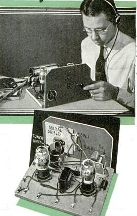
80 Years ago, the cover of the December, 1934, issue of Short Wave Craft featured this pocket portable one-tube superregenerative receiver covering the 49 meter shortwave broadcast band. According to the article, the receiver was able to pull in Europe without an antenna. And when tested with a short antenna in the magazine’s offices in a steel frame building in New York, the set picked up “stations galore.” The article notes that the receiver’s superregenerative circuit had one serious drawback: It radiates a very strong signal. The article therefore recommended that “it be operated only in the less congested areas where there are few short-wave receivers and where the danger of interfering with others is nil.” In other words, this particular circuit probably wouldn’t pass muster under Part 15 of the current FCC rules as an incidental radiator.

The author of the article is George W. Shuart, W2AMN, later W4AMN. He also wrote several articles for QST in the late 1930’s through the 1960’s.  His last contribution to QST appears to be a “Hints and Kinks” item in August 1978 for a CW filter.  A 1946 QST article includes a biography which notes that Shuart had been licensed since 1928, and had written numerous articles for beginners, a result of which was that many amateurs got their start from his articles. It also revealed that Shuart was employed by Hammarlund as its Advertising and Sales Promotion Manager. He was the author of the 1937 Radio Amateur Course
published by the same magazine in which appeared this one-tube radio.

The 1934 article provides two possible solutions for carrying the batteries for this pocket radio. The filaments run on two penlight cells, and the B battery can be as low as 22-1/2 volts. One solution is to make the B battery out of penlight cells bundled together and carried in a pocket. The other alternative is to mount them on a strap “which forms a belt that can be worn around the waist. This is an old stunt used in stage tricks.” A picture of this arrangement is shown in the article, and I would advise against wearing this type of battery while visiting an airport.


Click Here For Today’s Ripley’s Believe It Or Not Cartoon


1924 Monodyne One Tube Radio

Monodyne

This one tube radio is shown in an ad from 90 years ago, from the December 1924 issue of Radio News.  The ad for the National Airphone Corporation features the Monodyne, billed as “one of the most radical advances in Radio engineering. Parts heretofore considered essential are omitted with no loss of efficiency.” One customer reported hearing a broadcast from over a thousand miles away “like talking over the back fence.” It sold for $10, without the tube, headphones, or battery.

I haven’t been able to find any schematic or other details about this little radio. gifarmer.com has some information, including a photo of a nice surviving example. The radio came with two coils, one to cover 150 to 400 meters, and the other to cover 500-1000 meters. That works out to 750 kHz through 2 MHz, and 300 to 600 kHz. Presumably, those band edges were not exact, since there were stations between 400 and 500 meters, such as WLW on 423 meters (710 kHz) and WMAQ on 448 meters (670 kHz).


Click Here For Today’s Ripley’s Believe It Or Not Cartoon


The LFR: 1920’s-1960’s Air Navigation

From the late 1920’s until the 1960’s, an important tool for air navigation was the Low Frequency Radio Range (LFR).

At its peak, there were about 400 LFR beacons in the United States, and many more worldwide. Each station consisted of a transmitter being fed into two directional antennas. One antenna was sending the Morse letter “A”, dot dash. The other antenna was sending the letter “N”, dash dot. The two signals were synchronized so that the two signals alternated. At four directions from the station, the two signals blended to produce a constant tone. If a plane was off this course in one direction, the pilot would hear the “A” start to get stronger. Off course in the other direction, the “N” would get stronger.

Aeronautical charts such as the one shown here would show the letter that would be heard in each of the four quadrants. Here, in the quadrants south and north of the station, the pilot would hear the letter “N”. In the east and west quadrants, he would hear the letter “A”. On the shaded lines, the pilot would hear the continuous signal. These “beams” would be about a half block wide near the station, and as much as several miles wide far from the station. Most air navigation followed routes along these beams. The course a pilot followed would be along airways connecting the stations, and flying cross country would be a game of “connect the dots” as the pilot flew from one station to the other.

Every thirty seconds, the “A-N” signal would be replaced with the call letters of the station, in this case, RL, which would also be transmitted in Morse.

Despite the simplicity of the system, the accuracy was enough to use for instrument landings, and instrument approaches using the LFR beacons were published for many airports.

For the pilot, only a normal radio receiver was required. In later years, more sophisticated receivers were employed, which would show the pilot visually whether he was on the “A” side or the “N” side of the beam. But in most cases, the pilot navigated by listening to the signal in his headphones.

LFR station using Adcock antenna (Wikipedia photo).

LFR station using Adcock antenna (Wikipedia photo).

Most of the stations operated between 190 and 535 kHz, with powers of up to 1500 watts. Early stations used crossed loop antennas, but Adcock antennas (phased verticals) were used in most later stations.

Directly above the station, there was an inverted “cone of silence” where the directional signal disappeared. Even in times of no visibility, the pilot would know that he had passed over the beacon when the signal disappeared.

Starting in the late 1940’s, the LFR began to be replaced by the VHF Omni Range (VOR). While the VOR required a special receiver in the aircraft, it was superior in that it could be used to “fly a beam” in any direction from the VOR station, rather than just the four possible with the LFR.

bc1206

Photo courtesy of Ian O’Toole, VK2ZIO, Kurrajong Radio Museum. Used by permission.

Shown here is a BC-1206C Range Receiver, which would have been installed in the aircraft for the purpose of receiving the beacons. This radio, manufactured by Setchell Carlson, Inc., of St. Paul, Minnesota, is a five-tube superheterodyne.  As you can see from the schematic, it’s not much different from a standard broadcast receiver.

REFERENCES

Click Here For Today’s Ripley’s Believe It Or Not Cartoon


War QRM A Hundred Years Ago

QRM

A hundred years ago today probably marks one of the first times that QRM (radio interference) made the editorial cartoon pages.  This example, from the Richmond Times-Dispatch, December 8, 1914, depicts the interference to U.S. commercial stations from the warships patrolling just outside the U.S. coast.  The signals from the British ships were the primary culprits in causing interference to U.S. stations.


Radio Coverage of Pearl Harbor


imgHandler

USS Shaw at Pearl Harbor. Defense Department Photo.

Contrary to popular belief, the networks never broke into live programming to announcing the attack on Pearl Harbor on December 7, 1941. The first broadcast announcement came at about 2:30 Eastern Time on CBS, during a scheduled newscast.

But you tell me that you’ve heard an announcement breaking into a symphony mid-note, with the words: “We interrupt this program to bring you a special news bulletin. The Japanese have attacked Pearl Harbor, Hawaii by air.” This was actually from a record produced by CBS in 1948. The second sentence came from an actual broadcast later in the day. You can hear the original at this link.

There was apparently no recording made of the first announcement, and there was apparently no interruption of regular programming.

A recording from Minneapolis CBS station WCCO  is available at RadioTapes.com.  While there’s no time stated on the WCCO recording, this was apparently recording during the break in the New York Philharmonic concert, which started at 3:00 Eastern Time.  Therefore, the WCCO recording probably starts at about 3:30 Eastern Time.

References


German and British Amateur Radio Stations on the Air During WW2

Chart showing German amateur frequency bands, 1944. DASD-CQ, September 1944.

Chart showing German amateur frequency bands, 1944. DASD-CQ, September 1944.

It’s widely believed that amateur radio went off the air for the duration of World War II. That was certainly the case in the United States and Canada, as well as most of the warring countries. Some neutral countries remained on the air. For example, Portuguese hams remained on the air, and much of South America was still engaging in amateur radio as usual.


But strangely enough, the major exception was Nazi Germany.  German stations were ordered off the air after commencement of hostilities in September 1939.  But soon thereafter, many stations were granted a special wartime license, known as Kriegsfunkgenehmigung.  QST for April 1940 carried the following announcement sent from Chris Schmelzer, D4BIU:

There seems to be a widespread misunderstanding concerning the activities of German amateur stations to-day. According to a statement made by our government, all sport activities, etc., will be continued during the war to as large an extent as possible. Due to this, amateur stations D4ACF, D4ADF, D4BIU, D4BUF, D4RGF, D4TRV, D4WYF, D4HCF and D4DKN have been relicensed recently. More licenses will follow shortly. The stations are supposed to carry on strictly in the usual manner.

The website of the Foundation for German communication and related technologies contains copies of many wartime issues of DASD-CQ, the journal of  the German national amateur radio society, Deutschen Amateur-Sende-und Empfangs-Dienstes, which continued publication throughout the war.   From recording calls contained in that journal, the author of the web page counts at least 86 active call signs through 1944.  And DC5WW has provided a list (the source of which is not clear) of all licensed stations as of August 1944.  These include a number of stations licensed only for 10 meters.  And a collection of 1943 German QSL cards can be found at the website of Radioclub Braunschweig.  In addition to the hams with transmitting licenses, a larger number of receiving licenses were issued to DASD members.  It appears that the DASD was tasked with approving licenses at this time.  A 1944 letter from DASD president Ernst Sachs to Heinrich Himmler explaining the importance of amateur radio is available online.

So it is clear that there were a significant number of hams on the air from Germany throughout the war.  Many of them, it seems, were using a receiver very similar to the National HRO.  In fact, the tuning condensers were manufactured by National and imported through Portugal.  When the German military believed that they were not up to military specifications, they were given to the DASD for distribution to hams for use in receivers using German tubes.

As shown on the chart above, amateurs were allowed to operate on 20 channels between 3500 and 3600 kHz, as well as 7000-7200, 14000-14400, and 28000-30000 kHz.  (Not surprisingly, the Germans called them kiloHertz rather than kilocycles at the time.)

One can only speculate as to why Nazi Germany allowed its hams to remain on the air when the free world was silent.  The author of this page offers two reasons, both of which seem plausible.  The first was to show the world a sense of normalcy.  Apparently, the idea was for those in the rest of the world to have the impression that life was going on normally.   Or, as the QST article above put it, “all sport activities, etc., will be continued during the war to as large an extent as possible.”

The other reason was more practical.  It was believed that hams and SWL’s could provide valuable propagation information.  Indeed, one source noted that both hams and SWL’s were required to keep duplicate logs and send one copy to the authorities for analysis.

According to that same author, there was apparently no political test for licensees.  There was no special requirement of adherence to Nazi ideology (at least, no more so than required of the general population).  While the original plan to issue licenses was apparently approved by the SS, the actual administration of the program was under the control of the Wehrmacht, whose concerns were presumably more practical than ideological.

Even more surprising is that there were a handful of QSO’s, during the war, between these German stations and British stations!  In 1944, the British government allowed a small number of hand-selected prominent hams back on the air.   Under this program, called “Plan Flypaper” the call signs G7FA through G7FJ were assigned and allowed to operate with 50 watts on 80, 40, 20, and 10 meters. Among these hams was Louis Varney, G5RV, who became G7FJ. The full details of this program, including the operating rules, can be found at the Southgate ARC website.

The participants in this program made numerous contacts with neutral countries, and a handful of contacts with German stations.  They were forbidden from calling German stations, but they were instructed to make the contact if a German station called them.  The purpose of this program was apparently two-fold.  First of all, the idea was to simply make themselves available in case any interesting information was received.  They had instructions, if an enemy station wished to send a message, to relay it to headquarters, and to inform the other station to contact them again the next day for any response.

The other idea was that if any Allied prisoners of war gained access to a transmitter, they would be able to make contact with one of these British stations.  Apparently, neither of these goals was realized.

Here’s another interesting article about amateur radio in Nazi Germany, by Prof. Bruce Campbell KG4CUL:  https://theconversation.com/nazis-pressed-ham-radio-hobbyists-to-serve-the-third-reich-but-surviving-came-at-a-price-90510


Click Here For Today’s Ripley’s Believe It Or Not Cartoon


1939 Floor Lamp Radio

LampRadio1939Seventy-five years ago, Popular Science, December 1939, showed how to make this handy radio to be clamped onto any convenient floor lamp (or simply be used as a standard table radio). It had a myriad of potential uses. “Mounted on a bridge lamp it provides a radio for card games; attached to a floor lamp beside your favorite chair it puts the evening’s programs at your finger tips; and fastened to a standing lamp in your bedroom it serves as a convenient bedside set.”

Frankly, the “floor lamp” feature sounds a bit like an afterthought. The cabinet is hinged and includes cutouts to go around the lamp. A decorative band on the lamp, or a hose clamp, keeps the radio from sliding down.

The guts of the radio itself consist of a two-tube circuit consisting of two loctal tubes. A 7A7 serves as the regenerative detector, with the regeneration control used to control the volume. A 32L7 serves as the audio amplifier and rectifier. It’s an AC/DC set, with a 220 ohm resistor used to drop the line voltage to power the filaments. Because it’s run right off the AC line, there is a capacitor between the external antenna and the set, which the diagram reveals would otherwise be connected directly to one side of the line cord. The article contains a stern warning that this condenser “is extremely important, since it eliminates any possibility of blowing out the tubes or burning the primary of the antenna coil (which could start a fire) should the antenna wire or antenna lead accidentally come in contact with a grounded pipe or radiator” or, worse yet, some hapless person who happens to be touching the radiator.

I wonder how many people built such a radio. By this time, nearly every commercial radio sold was a superheterodyne, rather than the sometimes tempramental regenerative circuit used here. But still, a radio such as this one would be a pretty good performer, and quite suitable as a second radio after the big one in the parlor.

According to the 1942 Allied Radio Catalog (the new loctals were not yet shown in the 1939 catalog), the tubes would cost a total of $1.36. The least expensive table radio in the 1939 Allied catalog (a four-tube superhet) was $6.95.  Since most of the other parts could probably be scavenged from a broken radio, building this little two-tube set could represent a bargain for someone wanting to boast two radios in their home.