Category Archives: Radio history

1956 Four Transistor Superhet

1956JulyRadioElect

Sixty years ago this month, the July 1956 issue of Radio Electronics magazine announced, “This is it!” When the transistor had come out a few years earlier, it was predicted that it would eventually replace all of the tubes in broadcast radios. Other plans had been published for “transistor radios,” but they were merely crystal sets with a transistor used for audio amplification. All-transistor superheterodynes were just coming on the market, and the magazine announced that “at last, experimenters and hobbyists may construct their personal all transistor radio–one that can fit into a shirt pocket!

The set, constructed in a 29 cent clear plastic box, was powered by three penlight cells that were said to last up to 600 hours. Unlike earlier “self-contained” sets, this one required no external antenna, and had been tested in many different locations, such as walking along the street, in a steel building, or even in a cellar.

The set used four 2N112 transistors. The author reported picking up 20 stations in the New York area, and extolled readers to build one. “You will find plenty of use for it since you can keep in touch with the ball games, news flashes, your favorite concerts, etc. When carried in a shirt pocket, everything remains hidden except for the hearing-aid earpiece.”

Click Here For Today’s Ripley’s Believe It Or Not Cartoon


WLS Radio In The Barn Club, 1941

1941WLS

WLS Chicago billed itself as the Prairie Farmer Station, as shown in this ad that appeared in Broadcasting magazine 75 years ago today, July 28, 1941.

The ad reported that the station’s Bulletin Board program at 6:30 AM included weather, livestock estimates, crop news, and other items of interest to farmers. Many farmers wrote to the station to report that they had radios in their barns and listened as they did their chores. In response, the station formed a “Radio in the Barn Club” with certificates of membership.

Certificates were issued to almost 2000 farmers in 14 states: Pennsylvania, Tennessee, Ohio, California, Minnesota, Mississippi, Missouri, Texas, Iowa, Illinois, Indiana, Michigan, and Wisconsin.

The WLS call letters were first used in 1924.  At the time, the station was owned by Sears, and the station’s call letters boasted the World’s Largest Store.  The station was sold to Prairie Farmer magazine in 1928, which owned it until the station was sold to ABC in 1960.

Click Here For Today’s Ripley’s Believe It Or Not Cartoon


1976 Temporary CB License

1976CBtemporarypermit

Forty years ago, the United States was in the midst of the CB craze. The eleven meter band had been set aside for the Class D Citizens Radio Service in 1958, and it was initially a relatively useful service for short-range communications. But during the 1970’s, it became so wildly popular that every channel was almost continually filled with signals of varying strengths, so that only the closest and most powerful could break through. Back in those days, tuning through the 27 MHz band revealed a cacophony of heterodynes every 10 kHz along the dial, night and day.

CB’s also required a license, and at some point, the FCC was hopelessly overwhelmed. A few years later, they gave up, and licensed everyone in the United States under a “licensed by rule” arrangement. Many people ignored the license requirement, but those who went by the rules faced delays of months before the license arrived in the mail.

As a stopgap measure, the FCC in 1976 allowed for interim licenses. After you mailed in the license application, you filled out a second form, which you retained for your records. You even assigned yourself a call sign. The call started with K, followed by your initials, followed by your ZIP code. So in my case, I would have been KRC-55418.

Both the license application and the interim license were contained in the box when you bought a CB. But if you didn’t have a copy, the July-August 1976 issue of Elementary Electronics contained a copy.  Apparently, the size of the form had to be right, so the magazine instructed you to carefully cut the page to exactly 8 x 10 inches, and follow the instructions.

After you certified, under penalty of imprisonment, that you had mailed the form and the $4, that you were over 18 and not the representative of a foreign government, and weren’t in any prior trouble with the FCC, you assigned yourself the call sign, and you were on the air.  The back of the page contained a summary of the rules that you were to scrupulously obey.

Click Here For Today’s Ripley’s Believe It Or Not Cartoon


Direction Finding With An AM Radio

Portable radio mounted on base for direction finding.

Portable radio mounted on base for direction finding.

Sixty years ago this month, the July 1956 issue of Popular Electronics carried an excellent tutorial on how to use a portable AM radio for direction finding.

Most AM radios, both then and now, are very directional in that there is a “null,” or spot where the signal fades out, on each side of the built-in antenna.  You can demonstrate this by tuning to a relatively weak AM station and then slowly rotating the radio.  You will find that there are two spots, 180 degrees apart, where the station disappears or becomes very weak.  If the radio, like most portables, has an internal loopstick antenna, these are the points where the long narrow antenna is pointing directly at (or away from) the station.

You can use this principle to determine your location.  Even with a very cheap radio, you can usually establish your location with astonishing accuracy.

Detail of direction finding mount for portable radio.

Detail of direction finding mount for portable radio.

The Popular Electronics article shows how to construct a rotating mount for your radio.  You strap the radio in place, turn it for the minimum signal, and the pointer on the mount shows the bearing to or from the station in degrees.  For example, if the station’s null is at 45 degrees, then you can draw a line on a map over the station with that same angle from north.  In other words, in this example, running NE-SW.  Your current location is somewhere along that line.

By repeating this process with a second radio station, you will have two lines drawn on the map.  The point at which the two lines intersect is your current location, sometimes to astounding accuracy.

The mount shown in Popular Electronics is for a more or less permanent installation in a boat.  But this is not necessary.  In most portable radios, the antenna is mounted parallel with the outside case, usually with the longest side.  Therefore, it is possible simply to use the radio itself as a straightedge:  Align the map with the Earth, in other words, place the top of the map toward the north.  Then, rotate the radio so that the signal disappears.  With the radio at the same angle, place one edge over the station’s location and draw a straight line on the map.  Your location is somewhere along this line.

Then, repeat the process with a second station.  The point where the two lines come together is your location.  To confirm your location, you can repeat the process with a third station.  If the three lines come together very close to the same point, then you can be quite certain that the location was accurate.  If one of the lines doesn’t seem to agree, then you can repeat the process with a fourth station, and ignore the reading that doesn’t seem to match the others.

With a bit of practice, you can find your location very accurately.  In an urban area, by using 3 or 4 local stations, I have identified my location within a hundred yards or so.  In a rural area, where the stations might be further away, the accuracy will not be quite as great, but you should be able to locate yourself within a fraction of a mile.

The Popular Electronics article contains instructions on disabling the receiver’s automatic volume control (AVC), because in the case of a strong station, the radio might keep playing at full volume even with the station nulled out.  However, it is not necessary to modify the radio.  Most stations, unless they are very strong, will show a null even with the AVC functioning.  And for those stronger stations, you can compensate by tuning the radio slightly off frequency.  For example, if the station you are trying to locate is at 800 and you can’t get a null, you can reduce the signal strength simply by tuning to 810.  You’ll still hear the station with the radio properly oriented, but the signal will be weak enough that you will be able to detect the null.

Of course, for this method to work, you need to know the exact transmitter location of the radio stations you plan to use.  These often differ from the location of the station’s studio and office.  In some cases, they are many miles from the station’s city of license.

Fortunately, in the United States, this information is easy to obtain from the FCC website.  You can search for a particular station, for all stations within a state, or all stations within a certain radius of a given location.  When you click on the station’s call letters, you will be given the exact latitude and longitude of the transmitter.  (Transmitter locations of most AM stations are also shown on aeronautical charts, since pilots still use this method of direction finding.)

Direction finding, even with a very cheap AM radio, can give amazingly accurate results.  It is certainly not as convenient as other methods, such as GPS.  But in an emergency, it should not be overlooked as a backup method to determine your location.  It requires very little equipment (just a radio, map, and pencil).  It also requires a bit of practice beforehand, since you need to learn the characteristics of the radio you will use.  And it requires knowledge of the location of some local transmitters.  But if you can locate those transmitters on your map, you can also locate yourself.

As I mentioned, I’ve been able to determine my own location within a hundred yards by knowing the exact locations of local radio stations.  But even without an exact knowledge of their location, I was able to locate myself, at night, within about 30 miles, simply by using the approximate location of strong distant stations.  For example, I know that WBBM’s transmitter is in or near Chicago.  I know that WSM’s transmitter is in or near Nashville.  I know that CFZM’s transmitter is in or near Toronto.  Even though I did not know the exact locations of these transmitters, when I used this method at night, I was able to locate myself within about 30 miles.  There’s probably little practical application for doing it this way, since it’s unlikely that someone would find themselves not knowing what state they are in.  (However, it should be noted that before the invention of accurate chronometers, most mariners wouldn’t know their location that accurately.)  But it is still rewarding to know that you can determine your location on Earth with such primitive equipment.

Click Here For Today’s Ripley’s Believe It Or Not Cartoon


July 20, 1956 CONELRAD Test

Milwaukee Civil Defense Director Don E. Carleton and Col. Anthony F. Levno assess damage after simulated attack on Milwaukee. Milwaukee Journal, Jul. 20, 1956.

Milwaukee Civil Defense Director Don E. Carleton and Col. Anthony F. Levno assess damage after simulated attack on Milwaukee. Milwaukee Journal, Jul. 20, 1956.

Today marks the 60th anniversary of what was, as far as I’ve been able to determine, the only nationwide test of CONELRAD, the system designed to give Americans emergency information about a nuclear attack.

As I wrote in a previous post, all radio and TV broadcast stations in the U.S. left the air at 3:10 PM Eastern Time.  Designated stations came on the air on 640 or 1240 kHz, alternating between transmitters to confuse enemy bombers.  In some cities, such as Milwaukee, local exercises were conducted in conjunction with the CONELRAD test.  In the photo shown here, civil defense planners are examining the hypothetical ruins of Milwaukee.

Click Here For Today’s Ripley’s Believe It Or Not Cartoon


Niela Goodelle, 1936

1936JulyRadioGuide

Eighty years ago, this day’s issue of Radio Guide magazine, July 18, 1936, featured Niela Goodelle.

Born Helen Goodell, a friend remarked that her name “reeked of the kitchen,” and suggested she change it.  She turned her first name around and spelled it the way it sounded, and added an “e” to her last name.  The magazine described her as a welcome addition to any broadcast who had carried herself to the topmost pinnacles of radio fame.

According to the Internet Movie Database, she died in New York in 1988.

Here, she performs “Ten Pretty Girls.”

Click Here For Today’s Ripley’s Believe It Or Not Cartoon


First Televised Wedding, 1931

1931JulyTVNews

The first ever televised wedding took place 85 years ago, as shown here from the July-August 1931 issue of Television News.

The bride and groom, Grace Jones and Frank Du Vall were wed by Dr. A. Edwin Keigwin of the West End Presbyterian Church over the airwaves of W2XCR-WGBS. The video was transmitted over W2XCR, with the synchronized audio being transmitted over WGBS. The magazine reported that thousands of visualists were trilled by this marvel of modern science.  Du Vall was apparently a station engineer

The television studio and 500 watt transmitter were located at 655 Fifth Avenue, New York City. The station used a mechanical system employing a strong arc light with a rotating disc with a “flying spot” to do the scanning. The visual pickup consisted of fixed photocells. The more conventional system at the time placed the spinning disc in front of the photocell. The system used by W2XCR essentially consisted of a beam of light that scanned the subject, synchronized with the spinning disc on the receiver. The system used 60 lines and scanned 20 pictures per second.  The general idea is shown in the illustration here:

1931JulyTVNews2

The sound was sent by wire to WGBS at Astoria, Long Island.  According to the Spring-Summer 1931 issue of White’s Radio Log, WGBS operated on 600 kHz with 250 watts of power.  The station’s call sign represented its owner, Gimbel’s Department Store, and the station is the predecessor of WINS.

 W2XCR, licensed to Jenkins Television Corporation, operated on 2000-2100 kHz or 2750-2850 kHz.

According to the 1940 census, the couple was happily married and living in Essex, New Jersey, on their ninth anniversary.  The clergyman, Dr. Keigwin, appears to be the author of the 1899 hymn, The Someday By and By.

Click Here For Today’s Ripley’s Believe It Or Not Cartoon


1936 Code Oscillator

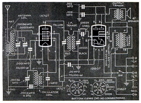
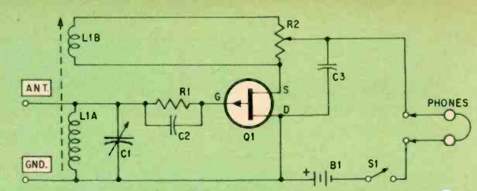
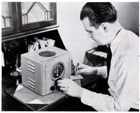
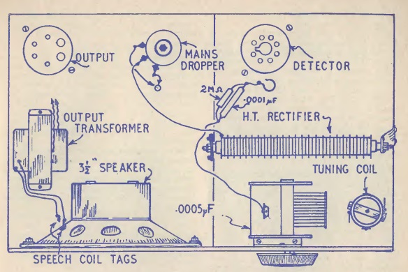
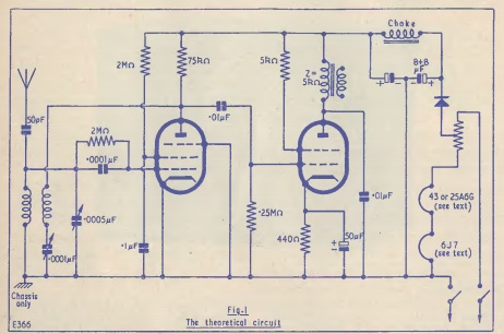
1936JulyPS11936JulyPS2Eighty years ago this month, the July 1936 issue of Popular Science contained the plans for this code practice oscillator.  The main feature was that it required neither headphones nor a battery, since it had sufficient volume to drive a speaker, and ran off household power.

As shown in the schematic, it used a single dual tube, a 12A7, with one half serving as rectifier and the other half as oscillator.  The 12 volts for the filament was supplied with a curtain burner line cord.

Click Here For Today’s Ripley’s Believe It Or Not Cartoon


1966 International Crystal Model MO-23 CB

1966JulyPEIntlMO23

When I first saw this ad from the Popular Electronics issue from 50 years ago this month, July 1966, I was amazed that they had achieved such a level of miniaturization, until I looked closer.  This is an ad for the Model MO-23 CB radio from International Crystal, which was so compact that it could hide under the dash, in the console, or in the glove compartment. As you can see, the radio isn’t much larger than the microphone.

Closer examination reveals that only the control head is inside the car. As with most two-way radio equipment of the 40’s through 60’s, the guts of the radio was in the trunk. The ad notes that “technically speaking, the MO-23 combines the best advantages of tubes and silicon transistors,” since the control head and power supply were transistorized, but the actual transmitter and receiver used tubes.

At least one example of this radio made it to market, since I did find this e-bay listing for one.  It shows the trunk unit, with at least nine tubes. Three transistors mounted at the back are probably part of the power supply to convert the car’s voltage to the B+ required by the tubes.

Click Here For Today’s Ripley’s Believe It Or Not Cartoon


1970 Broadcast Preamp

1970JulyEE

The listener shown here, on the cover of the July-August 1970 issue of Elementary Electronics, is listening to her Hallicrafters S-120A “Star Quest” receiver, which had just come out. It was a transistorized version of the S-120, and according to a sidebar in the magazine, it incorporated features found only on more complex and expensive receivers. It tuned the broadcast band, as well as 2-30 MHz shortwave, and included a BFO for tuning in CW and SSB.

But she wasn’t tuning the shortwave bands. She is actually listening to the broadcast band, and making use of the TennaBoost, the device sitting on top of the receiver, the plans for which were included in the magazine. The Tenna Boost was an external preamplifier. It was made from a commercial kit from International Crystal, but modified with the external ferrite loop. The amp was said to provide 30 dB gain, with the loopstick providing an additional 10 to 20 dB. The result was that you would hear a station every 10 kHz along the broadcast band. The article stressed the importance of making sure the case was completely shielded, since without the cabinet being securely screwed together, the amp and loopstick would break into oscillation.

Click Here For Today’s Ripley’s Believe It Or Not Cartoon