Category Archives: Radio history

1956 British Two Tube Receiver

1956radioconstructor

This simple two-tube broadcast receiver appeared sixty years ago this month in the October 1956 issue of the British Radio Constructor magazine.

One tube serves as the regenerative detector, with the other tube serving as AF amplifier to drive the speaker.  The set uses what is called a “metal rectifier,” although a modern semiconductor diode would probably be much more reliable.

The set runs directly off the AC mains, and the article notes a number of safety precautions, and the article assures that “if the precautions mentioned are taken, and the receiver fitted in a wooden cabinet, it will be quite safe.”  In particular, in addition to being completely surrounded the an insulating cabinet, the article notes that all metal components must be insulated.  The knob on the tuning capacitor must be covered with a non-conductive knob (with the hole for the setscrew filled in with insulating material), the switch must not come in contact with the chassis. and the bolts holding the chassis to the panel must be covered.  The plans give instructions for wiring the set for either 110 or 250 volts.

1956radioconstructorschematic

Click Here For Today’s Ripley’s Believe It Or Not Cartoon


Knight Kit Star Roamer

1966octpe

Fifty years ago this month, the October 1966 issue of Popular Electronics carried this ad for the venerable Knight Kit Star Roamer receiver.  It used four tubes, a selenium rectifier, and two diodes to cover 200-400 kHz longwave and the broadcast band through 30 MHz.  It was an ideal first receiver for the shortwave listener.  Despite the low price, in contrast to similar sets of the era, it did contain a power transformer to keep the chassis isolated from the AC line.

In another post, I have a link to a review of this set.

Click Here For Today’s Ripley’s Believe It Or Not Cartoon


Science Fair Idea: Homemade Cardboard Box Speaker

1966octradiotvexp

The young scientist or engineer looking for a relatively simple but interesting project for the science fair could construct the homemade permanent-magnet speaker shown here.  It appeared fifty years ago this month in the October-November 1966 issue of Radio-TV Experimenter.

The speaker is constructed inside a cardboard box, which also serves as the sounding board (which the article incorrectly calls a “cone,” which it would be in a normal speaker).

The only other components, aside from a few pieces of cardboard and glue, consist of a permanent magnet and wire. Just as in a commercially manufactured speaker, a coil of is mounted on a form surrounding the magnet. When an audio signal is applied to the coil, it and the top of the box are made to vibrate.

The 1965 plans call for a magnet from a burnt out speaker, and this would still be a possibility.  These days, a more prolific source of powerful magnets would be from the drives of defunct computers, as shown in this video:

Suitable magnets are also available from Amazon or many other sources.  These plans call for a coil of 75 turns of 30-gauge enamel wire, although the exact wire size is not critical. The original plans call for using the speaker with a radio or television. The simplest way to make the connection to a modern radio or MP3 player would be through the headphone jack. Another option would be to use an inexpensive audio amplifier such as the one shown below:

The use of an audio amplifier would also allow the use of a homemade microphone, such as one of those shown in an earlier post.  And for another somewhat more complex homemade speaker (or microphone), see this post.

Click Here For Today’s Ripley’s Believe It Or Not Cartoon


1966 GE Rechargeable Portable

1966sepelecworldFifty years ago, the September 1966 issue of Electronics World showed this General Electric transistor portable with a rechargeable battery.  It came with a detachable base containing a clock, which also served as the charger.  The battery was said to power the set for up to twelve hours after an overnight charge.

As seen from the headline, one notable feature was the fact that the set contained integrated circuits, and GE engineers predicted that all of their products would contain IC’s by 1970.

Citing the set’s reliability, GE offered a three year warranty, including the battery.

Click Here For Today’s Ripley’s Believe It Or Not Cartoon


Radio On The Farm, 1926

1926septradioage

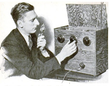
Shown here ninety years ago in the September 1926 issue of Radio Age magazine is Charles Ostrand, described by the magazine as a farm boy from Shawnee County, Kansas. He built the three tube set shown here in order to listen to helpful agricultural programs. The magazine reported that he had built several other sets for his neighbors.

This was not an unusual phenomenon. According to the magazine, there were already a million radios on the nation’s farms, and the U.S. Department of Agriculture predicted that the number would soon double. The radio, according to the magazine, was not just a device for entertainment. It delivered weather and market reports, as well as vital scientific information of use to farmers.

Click Here For Today’s Ripley’s Believe It Or Not Cartoon


1966 Adding Machine

1966addingmachine

Fifty years ago, electronic calculators were things of science fiction, and even adding machines were expensive. The little circuit shown here filled a few of the gaps. It appeared in the September 1966 issue of the British Radio Constructor magazine.

According to the author, the device was built in response to a request by a friend who needed an adding machine to be used at motor car rallies in order to tally the number of miles covered.

It consisted of a telephone dial, a relay, and an electromagnetic counter, the type that increased by one every time a pulse was applied. The telephone dial had normally closed contacts, so the relay was necessary to convert to individual pulses. Also, the author noted that the telephone dial contacts probably couldn’t handle the current required by the counter.

The end result was that the counter increased by one for each pulse. So if you wanted to add 3+3, you would dial 3 twice, and the counter would count to 6.

Two-digit numbers could be accomplished by dialing zero for each 10. So to dial 34, you would dial zero three times, and then 4.

Click Here For Today’s Ripley’s Believe It Or Not Cartoon


1936 Four Tube Portable

1936septps

The picnickers shown here in the September 1936 issue of Popular Science are enjoying a radio program, thanks to the compact portable broadcast set shown here. It was light enough to take in a car or canoe, worked indoors or out, and could provide loudspeaker volume. The four-tube battery superheterodyne design was said to rival the performance of any all-electric set, but the article promised that anyone could build it.

The tube lineup of the set was 1A6, 1A4, 1B4, and 1F4, and was powered by five batteries: Two 45-volt B batteries provided 90 volts to some parts of the circuit, and 45 to others. Filaments were powered by two 1.5 volt dry cells, and a 4.5 volt C battery was also used. The batteries were packed snugly in the bottom of the case, behind the 6-1/2 inch permanent magnet speaker. The cabinet, covered in luggage canvas, was both attractive and durable.

1936septpsschematic

Click Here For Today’s Ripley’s Believe It Or Not Cartoon


Science Fair Project: Atomic Frog Clock

1916septwirelessage

Here’s a picture of the time signal coming from the Eiffel Tower a century ago, as shown in the September 1916 issue of Wireless Age.

They were the results of experiments by one Dr. Lefeuvre, professor of physiology at Rennes University. The experiments were apparently carried out a few years prior, before the war, since they were also reported in the February 1913 issue of Popular Mechanics.

1913pmfroglegThe Eiffel Tower signals were received at a distance of 230 miles, and most remarkably, the mechanism for recording them was a frog’s leg, using the apparatus shown here.

Even though Prof. Lefeuvre conceded that there was no practical application to his system of “muscle writing,” it was regarded as a highly interesting laboratory experiment.

The sciatic nerve of the leg, cut below the knee, was spliced into the audio output of the receiver, with one end of the leg pinned securely to a base, and the other end connected to a lever. A pen recorded the impulses on the rotating drum.

Unfortunately, the “frog’s leg and its nerve do not retain their sensitivity very long,” precluding commercial application.

The experiment was, of course, an updated version of Luigi Galvani‘s 1780 experiment showing the frog legs could be made to twitch by application of static electricity.   Aspiring young mad scientists could probably develop an interesting science fair project along the same lines.  Instead of the Eiffel Tower time signals of a century ago, modern students in America could use the signals generated by WWV.  The now common “atomic clocks” rely on signals from sister station WWVB.  A bright student could quite easily construct a similarly accurate version, using the same user interface developed by Galvani over two centuries ago.  You might get some inspiration from this video:

Click Here For Today’s Ripley’s Believe It Or Not Cartoon


1966 One Transistor Regen

1966septei

One reason why simple transistor radio circuits proved challenging for early transistor experimenters was the low input impedance of bipolar junction transistors. This made it difficult to come up with an efficient circuit for a one-transistor radio.

But by 1966, the problem was largely solved by the appearance of the field effect transistor (FET), whose electrical characteristics were essentially identical to those of a triode vacuum tube. Fifty years ago this month, the September 1966 issue of Electronics Illustrated carried the plans for this one transistor regenerative receiver for the broadcast band.

The circuit used a Texas Instruments 2N3820, which sold for $3.75 plus shipping, and put out good headphone volume with a single transistor.

1966septeischematic

Click Here For Today’s Ripley’s Believe It Or Not Cartoon


Univ. of Minn. Electrical Engineering Bldg., 1926

1926septradiobroadcast

1926septradiobroadcastjanskyShown here ninety years ago is the Electrical Engineering Building at the University of Minnesota, from the September 1926 issue of Radio Broadcast magazine.

The magazine reported that the entire top floor of the building consisted of communication laboratories, principally devoted to radio instruction.  It was under the direction of Prof. C.M. Jansky, Jr., who believed that the program was the equal of any in the United States.

Click Here For Today’s Ripley’s Believe It Or Not Cartoon