Category Archives: Radio history

1967 Hart-65 One-Tube Transmitter

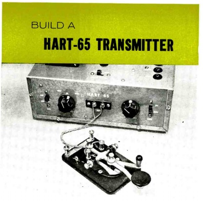
1967OctPEHart65Readers of this blog might remember the name Hartland Smith, W8VVD, currently licensed as W8QX.  We previously featured his steam powered transmitter, which appeared in Popular Electronics in 1965.  A number of his projects appeared in PE and other magazines, and the one showed here appeared in Popular Electronics 50 years ago this month, October 1967.

It was a transmitter for the novice which put out a very respectable 65 watts on 80 and 40 meters. It was an updated version of the author’s “Hart 25” transmitter which appeared in the magazine in 1955. Despite the increased power, the new version boasted the same price of about $20 for all of the parts.  The 1955 version had used a 6W6 tube to put out about 25 watts, along with a 5Y3 rectifier in the power supply.

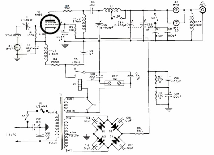
The 1967 version employed a 6HB5 TV horizontal amplifier, which was said to be highly efficient at cranking out RF. Tuning was accomplished by the simple expedient of tuning the pi network for maximum brightness of the pilot lamp. Another pilot lamp was provided for monitoring the current to the crystal, since too much current could fracture it. The article noted that smaller HC6/U crystals (and almost any modern crystal designed for solid-state circuits) should not be used because they would overheat, drift, and possibly shatter.

Cathode keying was used, but since the would mean as much as 700 volts across the key, a 6 volt relay was used for safety. The built-in power supply used a semiconductor bridge rectifier.

Smith recommended a full-size dipole antenna for the transmitter, rather than trying to use it with a random wire or multi-band antenna. He did have one insight that I independently discovered years later: “If an 80-meter dipole is too long for your piece of real estate, don’t hesitate to bend it around corners, or even droop the ends. Whatever the final arrangement, make certain that you have a total of 125′ of wire in the air.”  As you can see from my fan dipole from the June 2010 issue of QST, I’m not adverse to introducing a few zig-zags into an 80 meter dipole in order to squeeze it only a city lot.

He notes that the pi network should be adequate for keeping harmonics to a minimum. However, he also advises that if TVI is a problem, a low-pass filter in line with the antenna is in order. With today’s more stringent requirements for spectral purity, it would probably be a good idea to add the extra filtering even in the absence of TVI reports.

He reported that on the air, he worked numerous stations throughout the U.S. and Canada on both 80 and 40 meters. The rig had a “click-free pure d.c. note that was a joy to copy.” It was reported to be “rock-steady” on 80 meters, and “its 40-meter stability compares favorably with that of many low-cost VFO transmitters presently on the market.”

1967OctPEHart65Schematic

Hart-75 Transmitter. QST photo.

Hart-75 Transmitter. QST photo.

In addition to writing articles, Hartland Smith was the proprietor of Hart Industries, which produced a number of kits (and a few wired sets), including the Hart 25.  The 1955 Popular Electronics article included the address for Hart Industries for the kit, which included the pre-punched chassis.  Another Hart Industries kit was the similarly named Hart-75 from 1956. That transmitter was reviewed by Lew McCoy, W1ICP, in the February 1956 issue of QST. Even though the basic circuit was quite different from the PE transmitter (it used a 6AG7 oscillator and 807 final), it did have one common design feature, namely, the use of the relay for keying.

The 1956 model had an interesting twist, in that a DPST relay was used, keying the oscillator and amplifier almost simultaneously. But the circuit used something called “differential keying.” The contacts of the relay were set so that the oscillator came on slightly before the amplifier, and stayed on longer. The result was that chirp was greatly reduced.


1942: Putting High School Students to Work Servicing Radios

1942OctRadioRetailingSeventy-five years ago, these high school students in Watertown, N.Y., were seen as a resource that would help the radio industry deal with wartime labor shortages. An article in the October 1942 issue of Radio Retailing explained the plan by which high school students could be trained to fill the gap. A group of servicemen in northern New York were planning to run an intensive course in radio servicing, open to high school seniors with a year of physics. The course was to be offered five nights per week, two hours each night, for ten weeks, and was taught by local servicemen who would both lecture in the classroom and offer periodic trips to the shop to tackle real receiver problems.

Classes would be small, and after it was completed, one or two students would take over the shop of an owner who had entered the military, running the shop on an evenings-only basis. The student would be paid a weekly wage based upon volume. Repairs would be paid by check or money order. The idea was to keep the shop open as a community service, with enough income to cover the shop’s rent, overhead, and cost of equipment.

The students would continue to attend school during the day and work at night.


1957 Wireless TV Sound

1957OctPS1

Sixty years ago, domestic tranquility was restored in this household, as shown in this picture from the October 1957 issue of Popular Science.  Dad and Junior can watch the fight, while Mom and Little Sister work on the piano lessons.

This major breakthrough was accomplished after extensive testing by the editors of the magazine. Every TV owner had been waiting for the good news: “a simple way for each member of the family to turn the sound off or on, to suit himself, without annoying anyone else.”

The magic that made this possible was the inductive loop. Because the headset was wireless, “there’s no dangling cord to tether you to the console.” The headsets could be made in a couple of hours, and the magazine proposed three varieties.

1957OctPSLoopThe modification of the set and the installation of the loop was an almost trivial matter.  The magazine warned to unplug the set and let it sit for 15 minutes “for the tubes to cool off” (and hopefully for the electrolytics in the power supply to lose some of their charge).  Then, the lead to the speaker was snipped and hooked to the inductive loop, as shown here.  The magazine recommended adding the closed-circuit jack shown in the circuit here, so that the loop could be unplugged on those occasions when the speaker was desired.

The loop could be run under the carpet, as shown here, tucked away near the ceiling, or even placed in the joists in the basement below.  While reception was best when the headsets were at the same level as the loop, the magazine’s tests showed that any of these arrangements would work well.

1957OctPS2This loop formed the primary winding of a room-sized audio transformer.  The secondary windings would be in the individual headsets.  For the kids, the magazine recommended the spaceman style shown here, with the assurance that the kids would love them.

As revealed by the diagram below, these headsets were simplicity itself.  The coil was worn around the head, and hooked directly to the headphones.  The magazine suggested that Mom should be put in charge of suitably decorating the loop with colored tape.  No other electronics were necessary for these headphones for the kids.  The output of the coil was sufficient to drive the headphones.

1957OctPSHeadset

Mom and Dad warranted somewhat more discrete looking receivers, and these could be either of the models shown below.  Mom had a version similar to the kids’ version, but the loop was not worn.  It was apparently thought that she could set it in a convenient spot, and it was hooked directly to a small earphone.  The magazine noted that the earphone was so small that it could hardly be seen.  The only problem that might result would be forgetting to take it off before going to bed!

1957OctPSReceivers

Dad is seen using a slightly more complicated version, but still easily within the capabilities of anyone able to wire up a lamp cord.  It used a much smaller coil, amplified with the venerable CK722 transistor.  It was the size of the proverbial pack of cigarettes, and the two penlight batteries would keep it running for a thousand hours.

Those wishing to duplicate this idea today can save a great deal of coil winding time by using a telephone pickup coil instead of winding the coils for the individual receivers.  If a set of high-impedance headphones is available, it could be fed without any electronics.  The CK722 is more or less unobtainium, except at very high prices.  But any small audio amplifier could be put into service.  If you want to make your own, hundreds of circuits are available using the readily available 2N2222 transistor.


Fahnestock Clips: 1947

1947OctRadioNewsFahnestock

It’s been 70 years, so perhaps they’re out of catalogs. But it won’t hurt to print the coupon, send it in, and see if they still have any.  This ad for Fahnestock clips appeared in Radio News in October 1947.

Just in case they’re out of catalogs, there’s no need to worry.  You can still get them at Amazon:


Florence “Dot” Cheers Dawson

1923AustraliaXtalSetShown here in 1923 is 17-year-old Florence “Dot” Cheers of Brunswick, Victoria, Australia, listening to a crystal set accompanied by her young sister Jean. The set had been constructed by their brother Ronald.

Smoky and Dot Dawson, 1952. Wikipedia photo.

Florence went on to become a radio announcer known as “Aunty June” on station 3KZ in the 1930’s and 40’s.  She married Smoky Dawson in the 1940’s, and the two achieved fame in country music in both Australia and the United States.  The video below is a performance by Smoky Dawson.

Smoky Dawson died in 2008, and Dot died in 2010 at the age of 104.

The public-domain photograph, donated by Dr. Christina Cheers, is in the collection of Museums Victoria.


1947 Radio Parts Sales

1942OctRadioNewsCoverShown here as it appeared 70 years ago is the sales room of Concord Radio Corporation in Chicago. The picture appeared on the cover of the October 1947 issue of Radio News, which notes that complete stocks of radio parts, well displayed, were the secrets of the distributor’s success.


Taking a Break With the Radio, 1943

1943BeverlyAnnGrimm

Shown here in 1943 is eleven-year-old Beverly Ann Grimm of Buffalo, New York, taking a break from sweeping to listen to the radio. Beverly was largely forced to take care of herself and her five younger brothers and sisters. Her  mother was widowed, and worked all week as a crane operator with Pratt and Letchworth.  The mother’s name isn’t shown on the photograph caption, but according to the 1940 census, she was Thelma Grimm, and in 1940 lived at 60 Newman Street, Lackawanna, New York.  According to the photo caption, Mrs. Grimm was 26 years old in 1943, but according to the census, she was 26 years old in 1940.

The photographer was Marjory Collins of the Farm Security Administration. The photo, taken here from Wikimedia, was digitized by Yale, and more information is available at this link.  In the photo below, Beverly is shown bringing home the groceries purchased from her mother’s list.

I’m not able to make out the brand of the radio, which makes identifying it difficult.  If anyone has any clues, please let me know!  You can also find more information about this family and some of the artifacts in the pictures at this link.

1943BeverlyAnnGrimm2


The Banana Plug Goes To War

1942Oct12Life

The war effort of the United Nations depended on many minor miracles, and according to this ad in the October 12, 1942, issue of Life magazine, one of those minor miracles rolled off the assembly lines of the United-Carr Fastener Corporation of Cambridge, Mass.

That minor miracle was the banana plug, or as it was called here, the banana pin. The cause of war was calling Americans to every corner of the globe, and their communications depended on American radio equipment. And those sets contained banana plugs, lots of banana plugs. Hundred of thousands of banana plugs were in constant operation in planes, ships, and tanks, under all conditions of weather and battle. The banana plug was unseen and inconspicuous, but it insured the constant contact to keep the far-flung forces in touch with their commands.


RM2C Robert Melvey, W7HUX, 1924-1944

1942OctRadioNewsThe October 1947 issue of Radio News contains this report of a rare case of the FCC issuing a specially requested amateur callsign prior to the “vanity” callsign programs of later decades.

Ernest Melvey, formerly W7HVS, of 6416 Francis Avenue, Seattle, Washington, requested a waiver of the rule requiring calls to be assigned systematically.  Specifically, he requested the call sign of his son, U.S. Naval Reserve Radioman Second Class Robert Melvey, W7HUX, who had been killed in action, along with 132 other sailors, when the cruiser Nashville had been hit by a Japanese kamikaze plane on December 13, 1944.

USS Nashville after the kamikaze hit. Wikipedia photo.

The elder Melvey had made the request “in remembrance of the good times,” and the FCC was sympathetic to the father’s request to perpetuate his son’s call letters on the air.  The FCC granted the request, but “did not mean that it was relaxing its long adhered to policy against transfer of amateur call letters or requests for particular amateur calls.”

The younger Melvey is interred at Evergreen-Washelli Memorial Park, Seattle.

USS Nashville (CL-43) off the Mare Island Naval Shipyard on 4 August 1943.jpg

USS Nashville, 1943. Wikipedia photo.


1937 Remote Control Display

1937OctRadioRetailingEighty years ago,  Aeolian’s store in St. Louis (apparently a dealer in radios and pianos) managed to attract a big crowd to the sidewalk in front of their store window with this clever display, shown here in the October 1937 issue of Radio Retailing. The plate glass window contained four “buttons,” consisting of cards mounted inside the glass, each with the call letters of a radio station and the words “Place Hand Here to Tune.” Sure enough, when a visitor placed his or her hand on the glass, the console radio four feet away mysteriously tuned to the selected station, and the program came over a sound system piping the radio to the street. Over the course of three days, 5000 people placed their hands over the cards to tune in the radio. Many of them went into the store for a better look.

According to the magazine, the display was the brainchild of parts jobber Bob Ferree of Interstate Supply and Fred Pitzer of RCA. The cost of materials was $50, which the magazine proclaimed to be “cheap, when the timliness and effectiveness of the stunt is considered.”

The magazine carried the full schematic for the circuit, shown below. As most readers probably guessed, the circuit relied upon hand capacitance. Each foil pad was connected to an oscillator circuit, set so that the added hand capacitance would stop the oscillation. This triggered a relay, which in turn triggered a second latching relay which tuned the set’s remote control to the selected station.

Each of the cards had behind it 3.5 by 5 inch strips of tinfoil. Another card was glued to the back to conceal the foil. From each piece of foil ran a tiny 40-gauge enameled wire which ran to a relay unit hidden behind the set.  Each station required two tubes plus two relays, plus one rectifier tube to power the entire unit.

1937OctRadioRetailingSchematic