Category Archives: Radio history

Air King A-410 Radio-Camera

1947DecRadioRetailingIn 1947, Santa undoubtedly received many requests for one of these little beauties. It was obviously an idea before its time, but Air King obviously anticipated the cell phone camera. With the available technology of the day, they produced this combination camera-radio, the model A410, shown here in the December 1947 issue of Radio Retailing.

The camera featured a 50 mm lens, and could take either black and white or color pictures on standard 828 film.

The four tube radio ran on one flashlight battery and a 67-1/2 volt B battery.


1927 Medium Wave DX’ing Report

Meager putting the finishing touches on the Magnaformer.

Meager putting the finishing touches on the Magnaformer.

Ninety years ago today, the December 17, 1927, issue of Radio World carried the report of DX Hound Thomas F. Meagher. Meagher described his location in New York City as the one bad disadvantage he was saddled with, due to the proximity of so many local stations. But despite the disadvantageous location, Meagher was able to pull in over the course of six nights a total of 98 different stations in 43 cities. His log included stations as far west as WHO Des Moines and WCCO Minneapolis/St. Paul.

Meagher pulled this off with a loop antenna and the Magnaformer 9-8 receiver, the construction details of which were included in earlier issues of the magazine.

Meagher pointed out that he lived only 3/4 mile from WABC, and also close to other stations. The advantage of the Magnaformer was that it was able to “get in between” the stations with good selectivity. For example, he noted how he was able to go between WOR and WHN and pull in five out-of-town stations, WHJ, CFCF, WCCO, WFI, and WTAM. He reported that he took full advantage of the set’s loop antenna to null out the strong local stations.

1927Dec17RadioWorld2Meagher’s home at 7765 75th Street, Glendale, New York, is shown in the article. And lo and
behold, the same house is still recognizable in the Google Street View shown below.

1927Dec17RadioWorld3


1947 Philco Christmas Ad

1947Dec15LifeSeventy years ago, Santa was getting ready to head down the chimney with some of these Philco radios and phonographs shown in this ad from the December 15, 1947, issue of Life magazine.

The featured console was the Philco 1270, with a list price of $359.70. It featured an FM tuner, and also promised to let you say goodbye to record noise, with the “Philco Electronic Scratch Eliminator, the device that separates noise from music for the first time in the history of record-playing.”

If you wanted to add some scratches to those records to test the capabilities, the ad also featured two phonographs that could probably do the trick, models 1200 and 1201. The record was inserted into a slot on the front, and the ad promised “no more fussing with lids, tone-arms, or controls.” Model 1200 was just a record player, while model 1201 also featured a radio. Both were portable and could be carried anywhere.

You can see the 1270 in action at the following video.  While not mentioned in the ad, you can see from the video that the set also tuned 6-15.5 MHz shortwave.


1927 Soviet Fahnestock Clips

1927DecRadioL

1927DecRadioL2Ninety years ago, the Fahnestock clip was well established in the free world as a convenient method of making electrical connections. They were readily available wherever radio and electrical supplies were sold.

Soviet amateurs, on the other hand, were forced to use a bit more ingenuity, as shown from this issue, 1927 issue number 6 of Радио любитель (Radio Amateur) magazine. The article, by Engineer V.D. Romanov, shows how to make Fahnestock clips! While I can’t read the text, the diagrams are quite clear. The clips can be cut from sheet metal. Or for the truly enterprising Soviet ham, the article shows how to fabricate makeshift Fahnestock clips from wire!

There will undoubtedly come a day when the Fahnestock clip becomes unobtainium. When that happens, you’ll be able to make your own. In the meantime, you can get them at Amazon:


1917 CW Crystal Set

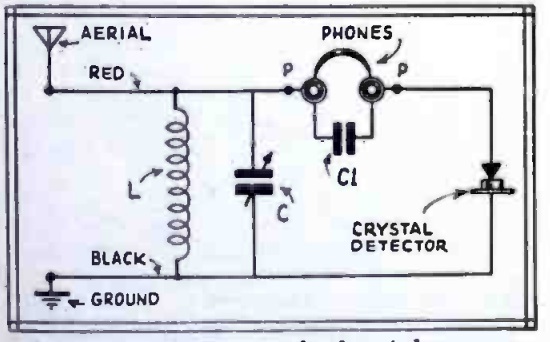
1917DecWirelessAgeA hundred years ago this month, the December 1917 issue of Wireless Age showed this method of received undamped waves (CW) with a crystal detector.  Unlike spark signals, the CW signals had no audio modulation.  Therefore, with just a crystal set, you can’t hear anything.

The conventional method to receive CW signals is with a receiver that has a BFO, an oscillator that mixes with the incoming signal.  When the CW signal is transmitted, you hear a tone which is the difference between the frequencies of the two signals.

This circuit uses a rotating variable condenser in the circuit.  The article includes alternate placements, but the idea is the same.  An audio frequency (the same as the frequency of the motor’s rotation) is imposed on the signal, and the code can be copied in the headphone.  The pitch you hear is equal to the frequency at which the capacitor is rotating.

We previously showed a similar idea from 1943 in this post.  In this circuit, CW can be copies by interrupting the circuit with a motor driving a commutator.


1937 Two-Tube Broadcast Set

1937DecPM1

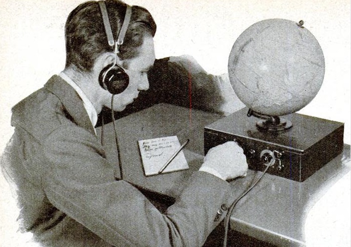
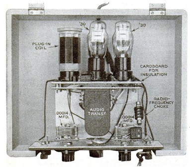
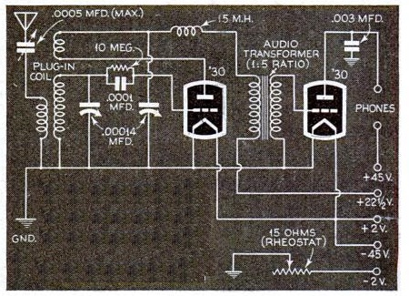
1937DecPM2Eighty years ago, the December 1937 issue of Popular Mechanics carried the plans for this simple two-tube portable broadcast set. It featured two type 30 tubes, one serving as regenerative detector and the other as audio amplifier to drive a set of headphones. The set could be taken on hikes or bike rides or to the ball game. And since the set ran a long time on a set of batteries, it was said to have a definite value in flood, hurricane, or earthquake areas.

The 22.5 volt B battery would last about six months. The filaments were powered by two flashlight batteries, which would be good for about five hours at a cost of only a dime each.

1937DecPM3


1958 Boys’ Life Radio Contest

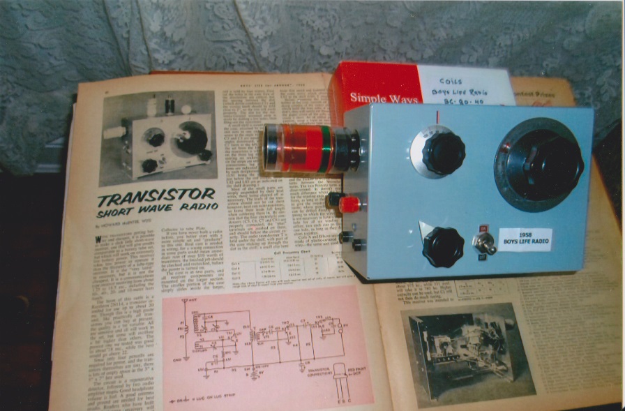
1957DecBLSixty years ago this month, the December 1957 issue of Boys’ Life announced the 1958 running of the magazine’s radio contest for hams and SWL’s.

According to the magazine, over 300 Scouts and Explorers at the 1957 Jamboree had been licensed hams, and most of them got their start with one of the BL radio contests.

The 1958 running had two classes for SWL’s. Class A entries used manufactured receivers or converted surplus sets. Class B was for scouts using homemade receivers they made themselves.

There was also a class for licensed hams, but the magazine noted that licensed hams were never eligible for prizes for winning contests. Hams were to call CQ BSA, and exchanged message number, RST, rank in scouting, and BSA region or country.  For the SWL categories, prizes ranged from ARRL memberships to receivers.

This year, the SWL contest was based entirely on the number of US and Canadian regions logged, number of states, and number of countries. Once a station in a particular region, state, or country was logged, there was no reason to log another. There were bonus points for logging all regions and all states, and any station qualified, whether it was broadcast, TV, FM, code, armed forces, police, amateur, or other.

The log had to include a 25 word written statement of either “I like short-wave radio because…” or “I’d like to get an amateur radio operator’s license because….”

Logs were to be signed by an adult certifying that the scout logged the stations by himself, alone.


Radio Electronics in Our Life by B.V. Fomin, 1957

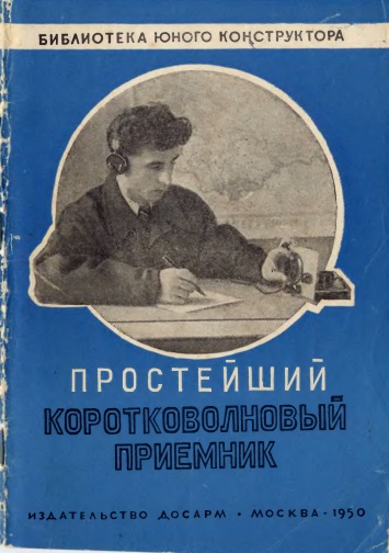
FominRadioelektronikaIt’s unclear exactly what’s going on in this picture, although there’s little doubt that the message being sent is critical to the success of the current five-year plan, and these comrades are making sure that the message gets through.

This is the cover of an intriguing little book entitled “Radio Electronics in Our Life”  by B.V. Fomin, published in Moscow in 1957 as part of a large series entitled the Popular Scientific Library.  This series, covering a wide variety of scientific and engineering topics, was published by the State Publishing House of Technical and Theoretical Literature (Гостехиздат; ГИТТЛ).

This and many other fascinating Soviet books and magazines can be found at Журналы СССР.


Wartime Radio Log

1942Dec5RadioGuideSeventy-five years ago today, the December 5, 1942, issue of Radio Guide included this listing of all of the broadcast stations in the U.S., Canada, and Mexico.

Numerous other such listings are available, most of which can be found at AmericanRadioHistory.com.  This particular listing is handy since it takes up only two pages, and provides an interesting snapshot of the broadcast band during the war years.

An alphabetical listing by call letters can be found in the December 19 issue.


Treasure Trove of Ten One-Tube Radios: 1942

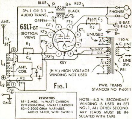
1942DecemberRadioCraft0Seventy-five years ago this month, Hugo Gernsback and the other editors of Radio Craft magazine undoubtedly anticipate the popularity of OneTubeRadio.com, since the December 1942 issue was packed with no less than ten different one tube radios!

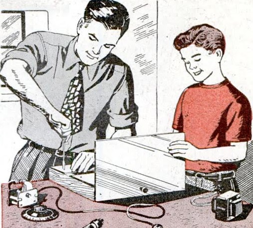
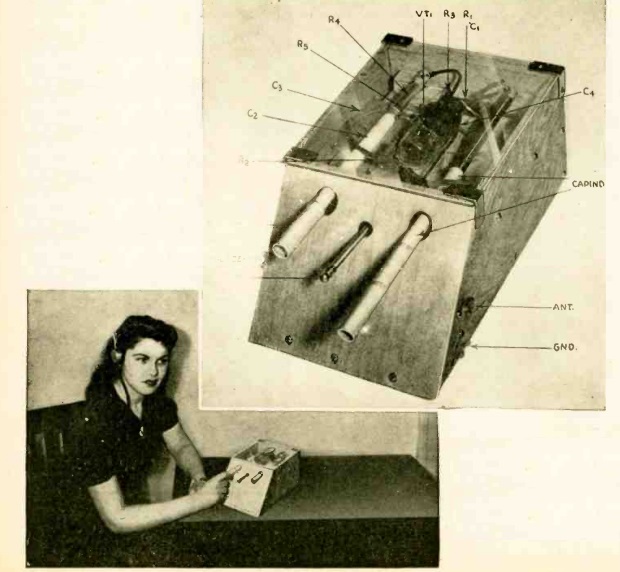
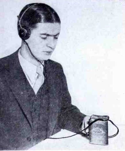
1942DecemberRadioCraft1The first is the simple set being operated by the young man shown above.   This set, the “easy one-tuber” was a broadcast set billed as being for any beginner: “Any schoolboy can build this unique one-tube set at a trifling cost. It is an easy little set to make and will bring in plenty of stations on the headphones.”

"Easy One Tuber" schematic.

“Easy One Tuber” schematic.

This set, which used a type 30 triode, was built in the venerable cigar box, and procurement of this chassis could be done at no cost: “Any cigar store will have an empty one to give you–or perhaps your father will hurry up and finish his latest box of cigars, if you tell him that you are about to build something really useful for once!”

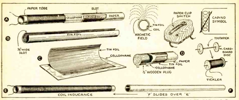
The tuning coil was tapped for variable selectivity. The article noted that the lower the clip was placed on the coil, the sharper the tuning would be. But if carried too far, volume would be reduced.

Regernation was adjusted by means of a variable tickler coil mounted inside the tuning coil. It could be rotated to place the set just on the verge of oscillation for maximum sensitivity.

The article recommended an indoor aerial wire of about 40 feet, but noted that stronger signals would be picked up with a longer outdoor aerial.

One-tube shortwave set.

One-tube shortwave set.

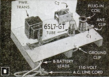
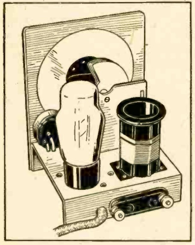
For the slightly more advanced student, the magazine next carried the “beginner’s one-tube short-wave set” shown at the top of this page and at the left, designed by Francis R. Harris, who noted that “broadcast wavelengths and the programs they carry are very interesting, but the real thrill of radio lies in the short wavelengths–the higher frequencies–on which it is possible to pick up programs of all kinds from the very ends of the earth!”

The set was “the simplest and the best breadboard style that we have yet constructed. It is designed for the absolute beginner who is neither radio man nor mechanic, and yet it will equal or better the performance of many more elaborate lay-outs.”

The use of plug-in coils allowed the set to tune 545 to 16 meters (550 kHz to 18 MHz). The only tools required were screwdrivers, diagonal cutters, long-nose pliers, wood tools, and a soldering iron.

The set used a type 33 pentode. While that tube was designed for AF applications, it apparently functioned well as a detector up to the promised 18 MHz.

1942DecemberRadioCraft3

The article recommended a 50 foot outdoor antenna, fed into the house with a porcelain standoff. “Don’t under any circumstances, use one of those flat contraptions that is supposed to go under the window.”

MorganReceiverThis set probably looks vaguely familiar to many readers.  While the circuit is not identical, the general layout and construction philosophy is very similar to Alfred Powell Morgan‘s one-tube receiver from the Boy’s First Book of Radio and Electronics.  Many radio hobbyists got their start after discovering this book in the elementary school library.  Morgan’s set is shown at the left, and has an uncanny resemblance to the 1942 model.

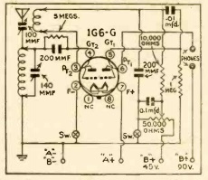
If that wasn’t enough for one tube radio fans, the magazine went further and included eight more “famous 1-tube circuits” shown below.

1942DecemberRadioCraft5

The seven shown on the page above are first the “Ultra-Audion,” “undoubtedly the most publicized circuit in radio,” the genesis of the regenerative circuit, which would tune all way down to 30,000 meters with appropriate coils and one tuning condenser.

The “Ambassador” was “without question the receiver that longest held the spotlight of popular interest.”

The “Interflex” was a design of Hugo Gernsback’s creation, using a crystal detector with one stage of audio amplification, with no need for transformer.

The “Megadyne” was said to be “of special interest to technicians,” and also combined a crystal detector with one stage of audio amplification.

The “Harkness Reflex” put the single tube to work twice, first as detector, and also as audio amplifier.

The “Solodyne” had been imported from Egnland, and was originally billed as “batteryless.” However, it simply combined the A and B batteries.

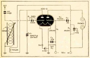
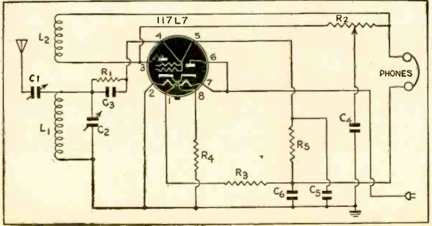
1942DecemberRadioCraft6Finally, shown here on the continuation page is the “Oscillodyne,” a super-regenerative circuit.

In addition to all of these one-tube sets, the issue also contains some two-tube receivers, as well as a few one-tube phono oscillators.