Seventy-five years ago this month, Hugo Gernsback and the other editors of Radio Craft magazine undoubtedly anticipate the popularity of OneTubeRadio.com, since the December 1942 issue was packed with no less than ten different one tube radios!
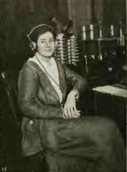
 The first is the simple set being operated by the young man shown above. This set, the “easy one-tuber” was a broadcast set billed as being for any beginner: “Any schoolboy can build this unique one-tube set at a trifling cost. It is an easy little set to make and will bring in plenty of stations on the headphones.”
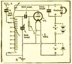
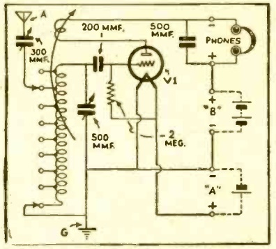
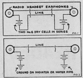
“Easy One Tuber” schematic.
This set, which used a type 30 triode, was built in the venerable cigar box, and procurement of this chassis could be done at no cost: “Any cigar store will have an empty one to give you–or perhaps your father will hurry up and finish his latest box of cigars, if you tell him that you are about to build something really useful for once!”
The tuning coil was tapped for variable selectivity. The article noted that the lower the clip was placed on the coil, the sharper the tuning would be. But if carried too far, volume would be reduced.
Regernation was adjusted by means of a variable tickler coil mounted inside the tuning coil. It could be rotated to place the set just on the verge of oscillation for maximum sensitivity.
The article recommended an indoor aerial wire of about 40 feet, but noted that stronger signals would be picked up with a longer outdoor aerial.

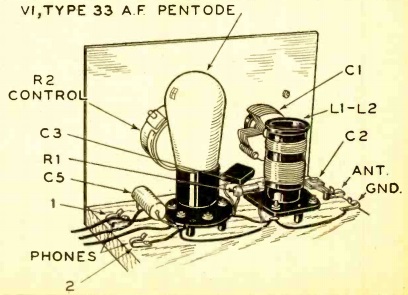
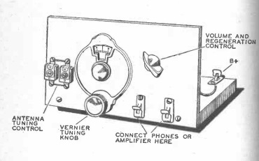
One-tube shortwave set.
For the slightly more advanced student, the magazine next carried the “beginner’s one-tube short-wave set” shown at the top of this page and at the left, designed by Francis R. Harris, who noted that “broadcast wavelengths and the programs they carry are very interesting, but the real thrill of radio lies in the short wavelengths–the higher frequencies–on which it is possible to pick up programs of all kinds from the very ends of the earth!”
The set was “the simplest and the best breadboard style that we have yet constructed. It is designed for the absolute beginner who is neither radio man nor mechanic, and yet it will equal or better the performance of many more elaborate lay-outs.”
The use of plug-in coils allowed the set to tune 545 to 16 meters (550 kHz to 18 MHz). The only tools required were screwdrivers, diagonal cutters, long-nose pliers, wood tools, and a soldering iron.
The set used a type 33 pentode. While that tube was designed for AF applications, it apparently functioned well as a detector up to the promised 18 MHz.

The article recommended a 50 foot outdoor antenna, fed into the house with a porcelain standoff. “Don’t under any circumstances, use one of those flat contraptions that is supposed to go under the window.”
 This set probably looks vaguely familiar to many readers. While the circuit is not identical, the general layout and construction philosophy is very similar to Alfred Powell Morgan‘s one-tube receiver from the Boy’s First Book of Radio and Electronics. Many radio hobbyists got their start after discovering this book in the elementary school library. Morgan’s set is shown at the left, and has an uncanny resemblance to the 1942 model.
If that wasn’t enough for one tube radio fans, the magazine went further and included eight more “famous 1-tube circuits” shown below.
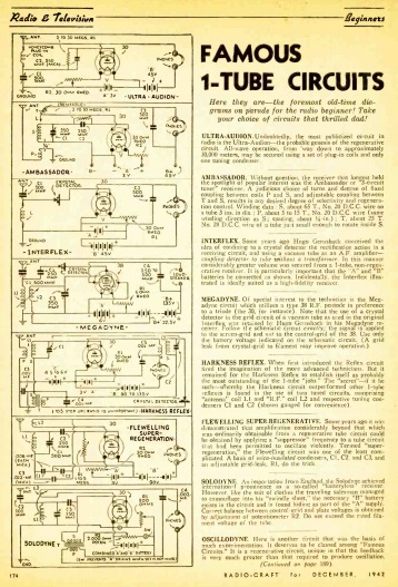
The seven shown on the page above are first the “Ultra-Audion,” “undoubtedly the most publicized circuit in radio,” the genesis of the regenerative circuit, which would tune all way down to 30,000 meters with appropriate coils and one tuning condenser.
The “Ambassador” was “without question the receiver that longest held the spotlight of popular interest.”
The “Interflex” was a design of Hugo Gernsback’s creation, using a crystal detector with one stage of audio amplification, with no need for transformer.
The “Megadyne” was said to be “of special interest to technicians,” and also combined a crystal detector with one stage of audio amplification.
The “Harkness Reflex” put the single tube to work twice, first as detector, and also as audio amplifier.
The “Solodyne” had been imported from Egnland, and was originally billed as “batteryless.” However, it simply combined the A and B batteries.
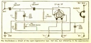 Finally, shown here on the continuation page is the “Oscillodyne,” a super-regenerative circuit.
In addition to all of these one-tube sets, the issue also contains some two-tube receivers, as well as a few one-tube phono oscillators.
 Sixty years ago this month, the December 1957 issue of Boys’ Life announced the 1958 running of the magazine’s radio contest for hams and SWL’s.