Category Archives: Radio history

Voice of America: 1944

1944JunePM2

1944JunePM1

Transmitter engineer flipping the switch at antenna farm to beam program to Europe.

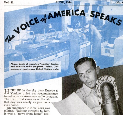
Seventy-five years ago this month, the June 1944 issue of Popular Mechanics highlighted the shortwave broadcasting efforts of the Office of War Information (OWI). The magazine dubbed the American shortwave stations the “Voice of America,” a name which would become official in following years.

The magazine noted that the Nazis had a head start on the radio war, since Germany had over a hundred transmitters spewing propaganda to the world. The United States had only sixteen, all under private ownership. But even though it took some time to get going, the OWI wass directing a 24 hour flow of news and information around the world. The magazine noted that America strictly adhered to factual news.

Jamming was rampant, and broadcasts were normally read at a hundred words per minute to compensate. When poor conditions dictated, this was sometimes slowed to 80 words per minute. The OWI knew that there were listeners. After the liberation of parts of Italy, a survey indicated that one in ten families heard allied programs, despite severe penalties for tuning in.


Dangerous Way to Listen to Radio: 1929

1929JunePMAccording to the caption of this picture from the June 1929 issue of Popular Mechanics, the gentleman shown above is merely “sick.” But he doesn’t look very good, and we suspect he may have already succumbed to electrocution.

He wanted to listen to the radio, but they didn’t want to drag the radio into his room. Nor did they want to run any wires. So someone came up with the bright idea shown here. There was already a perfectly good set of wires in place, namely, the house electric wiring. So they decided to put it into service by feeding the radio output into the power wires, and plugging in a set of headphones on the other end. A 2 μF capacitor was put in place as a gesture toward safety.

1929JunePM2

The first problem seems to be that it wouldn’t really work. Whatever audio made it through would be drowned out by the 60 cycle hum, assuming that the lighting current was AC, which it was in most of the country by that time.

And unless my back-of-the-envelope calculations are wrong, the capacitor will have a reactance at 60 Hz of only about 1300 ohms, meaning that a current of up to 90 mA could still flow through, which seems like plenty to deliver a lethal shock, especially if you’re placing the electrodes right next to the brain.

So in our estimation, this project is not one which should be attempted.  Kids (and adults):  Do not try this at home!


How to Read a Vernier Scale

1944JunePMVernierSeventy five years ago this month, the June 1944 issue of Popular Mechanics carried a lesson in the now almost forgotten art of reading a vernier scale.  With virtually any kind of instrument with an analog display, such as a caliper or micrometer, the vernier scale allows the human eye to make a much more precise reading.

The vernier display consists of two scales.  In the example shown above, the top scale is the main scale, and shows just over 5.3 inches.  (The zero on the bottom scale takes the place of the pointer which would be used on a non-vernier scale.)

The human eye, looking at this pointer, would undoubtedly conclude that the actual measurement is 5.35 inches, since the pointer is about halfway between the 3 and the 4.  But is it really 5.35, or is it 5.34 or 5.36?  You can’t really tell with the naked eye.

But the vernier scale makes eyeballing it easy.  You simply look at the bottom scale, and see which number is exactly lined up (or most closely lined up) with a number above.  In this example, the 6 on the bottom scale is lined up exactly with the 9 on the upper scale.  The number on the upper scale is not important–it’s only important that some number on the lower scale is lined up exactly.  In this case, the 6 means that we add 6/100 inch, meaning that the exact measurement is 5.36″.

Below, we see a vernier dial applied to a caliper.  In the picture on the right, the scales are flattened so that they can be viewed on the printed page.  The idea is the same.  The sleeve scale shows 0.3 inch, plus 0.12 on the thimble scale, since the center line is between 12 and 13.  The 5 on the vernier scale is lined up with the 20, meaning that we add .005 inch.  Thus, the measurement is .3 + .012 + .005 = .3125 inches.

1944JunePMVernier2


Radio fans are probably most familiar with the “vernier dial” shown at the left.  This one is available on Amazon and is called a “vernier dial.”  However, the vernier markings which are supposed to be on the tab on top are inexplicably missing.

The vernier scale is named after vernier acuity, the human eye’s ability to detect small differences in the alignment of a straight line.


1959 Underwater Speaker

1959MayPM3Sixty years ago this month, the May 1959 issue of Popular Mechanics shows an idea that surprisingly never caught on: underwater music. You’re swimming at the pool and listening to music. But when you dive under the water, you can no longer hear the music. The problem is easily solved by installing a speaker inside the pool. Because sound travels five times as fast in water, “music from the submerged speaker is more true-toned than one mounted in the air.”

And the project is quite simple. All you need to do is purchase a “submergence-proof speaker.” The magazine recommended the University MM-2F (UW), a 25 watt speaker which sold for about $40.

And lo and behold, if you search Amazon for “submergence proof speaker,” one is still available today, although it appears to be marketed toward industrial applications. It is shown here, and the full details are available at this link.  It appears quite similar to the model shown in the magazine.  The price is higher today than it was in 1959, although most of the increase is attributable to inflation.


1939 Two-Tube Shortwave Set & Three-Tube Marie Antoinette Radio

1939MayPS3Eighty years ago this month, the May 1939 issue of Popular Science carried the plans for this two-tube set, which was said to “bring in London, Rome, and Berlin as easily as local broadcasts.” The circuit was very efficient, since the two 6C6 tubes ran on a B+ voltage of only 3 volts for shortwave, or 1.5 volts for standard broadcasts. The tubes, although nominally 6-volt filaments, used 3.4 to 3.8 volts, as adjusted by the 10 ohm rheostat.

1939MayPS4

1939MayPS5For those desiring a slightly different radio experience, the same magazine also showed how to put together this three-tube “dressing table radio” concealed within a Marie Antoinette doll. The radio itself is concealed under Marie Antoinette’s dress. Atop is affixed a ceramic figurine. While the exact replacement is apparently no longer available, this Marie Antoinette salt shaker would undoubtedly work perfectly:


HCJB Transmitter Site, 1959

1959MayPEhcjbThis picture of the HCJB transmitter site at Pifo, Ecuador, appeared in the May 1959 issue of Popular Electronics. The magazine noted that the station was currently capable of transmitting on a single shortwave frequency with 50,000 watts, but would soon have the capability of transmitting on two frequencies simultaneously at 30,000 watts each.

For more information about the station, see our earlier post about the station’s history.


Line Voltage Booster

1979MayPEThis was by no means a new idea at the time, but the May 1979 issue of Popular Electronics shows a simple way to boost your line voltage. It employs a six-volt filament transformer wired so that it becomes an autotransformer, and the voltages on both coils add. So if you start with 120 volts, you wind up with 126. As the accompanying text explains, you might need to use some trial and error. If you wire it up and the voltage goes down by six volts, then you need to reverse the secondary windings.

While they are not common, 6 volt filament transformers are certainly not unobtainium, and you can get them from Amazon at this link:

If you need a slightly heavier duty version already assembled, then you can’t go wrong with an adjustable autotransformer (commonly known as a variac) like this one:


1934 Try-Mo Scout Shortwave Receiver

1934MaySWcraftScoutThe May 1934 issue of Short Wave Craft magazine included this ad for the “Scout,” a one tube shortwave set from the Try-Mo Radio Co., Inc., of 85 Cortlandt Street, New York.  The set sold in kit form for only $3.95, but the type 230 tube, batteries, and headphones would run an additional $4.25.  The set came with plug-in coils for shortwave, but a coil for the standard broadcast band would cost an additional 39 cents, probably a good investment in case the short waves were quiet.


1944 WERS Transceiver

1944MayQSTSeventy five years ago this month, the May 1944 issue of QST carried a construction article for this 112 MHz transceiver for the War Emergency Radio Service (WERS). The article was unique in that it showed how to “mass produce” the set in a high school shop class.

The Altoona, PA, WERS organization operating under call sign WKYU, had little appropriate equipment. Compounding the problem was the fact that few skilled amateurs remained at home to do the building. The problem was solved by setting up construction of standardized transceivers by radio and electronics students in the vocational department of Altoona High School. The school benefitted by having interesting and worthwhile lab work, and WERS benefitted by having a source of the needed equipment. In addition, the students who were involved in WERS also had particular pride in using equipment they themselves had built.

The circuit is a familiar one for VHF transceivers of the era. A 6J5 served as oscillator and self-quenched superregenerative detector, although other tubes could be substituted. A 6G6 pentode served as modulator and audio amplifier. Since wartime shortages meant that some tubes were not available, the article suggested substitutions for each.

1944MayQSTschematic


1929 Soviet Portable Receiver

1929SovietPortable1929SovietPortable2I wish I was able to read more about this 1929 Soviet portable set. But the text is in Russian, and the quality of the scan is rather poor, so I can’t even make out any words to give me hints. But this is obviously a portable receiver from ninety years ago, and some lucky comrade was able to put it together and pull in the signals.

The set appears to be a two-tube regenerative receiver which fits handily into a suitcase.  One tube servies as detector and the other as audio amplifier.  The circuit appears to be regenerative, with a tickler coil feeding the signal back into the main antenna coil.  Tuning is accomplished with a tapped coil and variable capacitor.  The cut-out in one corner is obviously to stash the batteries, and perhaps the headphones and antenna wire.

The plans for the set appeared 90 years ago this month in the May 1929 issue of Радио любитель (Radio amateur) magazine.

1929SovietPortableSchematic