Category Archives: Radio history

1959 Radio Sunglasses

1959SeptPELong before Smart Glasses were even a glimmer in some engineer’s eye, a Japanese visionary came up with these fashionable sunglasses that concealed a three transistor radio. They are reviewed here in the October, 1959, issue of Popular Science.

The circuitry was concealed in the arms of the glasses. A one-transistor RF stage was on one side, with a two-stage AF amp on the other side. Sound was produced by a small transducer, and a tuning control was on the RF side. It was powered by a tiny mercury battery.

According to the review, the set was remarkably sensitive, and picked up most of the New York stations from PE headquarters in Manhattan. Selectivity wasn’t the greatest, but it was more than adequate for separating most local stations.

The glasses are apparently no longer available, but you can still buy the Bluetooth speaker glasses shown below:


Selling Shortwave Sets, 1939

1939OctRadioRetailingThe outbreak of war in Europe on September 1, 1939, meant opportunity for American radio dealers, and the editors of Radio Retailing were quick to point them out in the October 1939 issue.

In particular, the magazine pointed out that the war revitalized the sale of shortwave sets. The article started with some common-sense tips on how to listen, noting that most of the stations of beligerent countries would be presenting only part of the story at best. It also gives the frequencies of some of the strong European stations and gives some pointers on how to sell shortwave sets to new customers.

The article points out, however, that many existing customers had sets that tuned the shortwaves, but that the owners rarely listened to them. With the heightened interest in war news, the magazine gave some ideas. First, it suggested that many buyers might need a better antenna to optimize reception. And even if there was no particular need for an upgrade, it suggested that a friendly service call might be in order. The customer could be instructed in how to tune in the signals, and there might be some services that are needed. The magazine pointed out that a weak tube might work perfectly fine for strong broadcast band signals, but not quite strong enough to pull in the shortwaves.


October 1, 1919: Hams Back On The Air

1919NovQSTA hundred years ago today, October 1, 1919, Amateur Radio Operators were once again allowed to transmit, after being required to dismantle their stations during the war. They were allowed to begin receiving earlier in the year, but the transmitting ban was not lifted until October.

The notification came to ARRL headquarters just as the October issue of QST was going into the mail. Apparently a notice was added to the copies mailed, but that does not exist in the online QST archives. The notice above appeared in the November 1919 issue of QST.

Another article in the magazine reminded readers that prewar licenses had all expired. Amateurs who held an unexpired commercial license could operate under that authority, but all amateurs needed to get a station license.

Despite clerical staff being short, the radio inspectors were making provisions to get licenses issued as fast as possible. In fact, the inspector was able to advise the applicant that he had passed and what his call sign was going to be, and he could start operating immediately.

It was recommended that applications be made in person, but for those who couldn’t make it to the inspector’s office, there was provision for licensing by mail. In Boston, for example, the inspector required all within 40 miles to apply in person. Those more than 40 miles away from the city were allowed to apply and take the examination by mail.


1939 Three Tube Portable

1939SepPS2This trio are pulling in stations from their campsite thanks to the three-tube portable described in the September 1939 issue of Popular Science. Just like the patio set described in the previous month’s issue, the set used three miniature tubes imported from England, although with the war just underway, it might have been hard to get more after the U.S. stocks were depleted. Apparently, the men had come to terms about taking turns with the headphones.

The author used a steel telescoping fishing rod as antenna by soldering a banana plug onto the end. The article noted that the connection could also be made by clipping a wire onto the end. In fact, if the wire were used, the set could be used in the boat, with the rod serving both to pull in stations and to pull in fish. In this case, however, an insulated handle would be needed for the fishing rod.

1939SepPSschematic


Heathkit CB-1

1959Sep59PE2We’ve previously written (here and here) about the Heathkit Model CB-1 CB transceiver. Sixty years ago this month, the September 1959 issue of Popular Electronics carried a review of the kit.

The magazine described the set as handsome and lightweight and convenient for use either at home or in the car. The set had a built-in 120 volt power supply, and could be used mobile with a vibrator power supply.

The set was easy to put together, but the magazine warned not to rush and try to do it in a single evening. During that sunspot peak, the author reported that stations from several time zones were heard. When operated from the car, a station a few miles away reported a good signal with high modulation.


1944 British One Tube Regen

1944SeptPractWireless75 years ago this month, the September 1944 issue of the British publication Practical Wireless carried the plans for this very basic wartime one-tube regenerative receiver. The set employed a 1D8GT dual tube, half of which served as detector, with the other half serving as AF amp, providing about 100 mW of audio to the speaker. With a ten-foot antenna, the set would easily pull in the BBC home, European, and armed forces services.

1944SeptPractWirelessSchematic


1969 AM-FM Portables

1969SepEI3Fifty years ago this month, the September 1969 issue of Electronics Illustrated reviewed a number of pocket (for large pockets, that is) portable AM-FM receivers.

The magazine noted that many such sets were showing up as loss leaders and prices below $10, and the article asked how these cheap models compared with more expensive brand names. The surprising result was that the cheap no-name sets performed as well as the more expensive models, although the more expensive sets were, in some cases, easier to tune and looked better. But the moral of the story was that these were a class of products where shopping strictly for price was the best strategy.


An Old Soviet Tube

1929RadioL

I’m not sure what this old tube is doing, but it appears on the cover of the September 1929 issue of the Soviet publication Радиолюбитель (Radio Amateur). One would think that the word written on the ground would add some context.  But according to Google translate, “скатертъюборога” means “tablecloth,” so that doesn’t seem to help.

Since I can’t think of any other reason why atheist Soviets would be showing Christian crosses, I assume that these are grave markers.  Modern Soviet tubes have replaced the old models, and this old tube is visiting his fallen comrades at the cemetery.  Perhaps he plans to have a picnic on the tablecloth.


1959 Radio/Intercom

1959RadioTVExp3
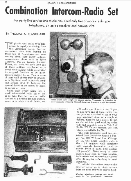
Sixty years ago, the occasional publication Radio-TV Experimenter carried this interesting project. As the enclosure, it used an already antique crank-type wall telephone as the housing for a radio receiver, but put the telephone back into service as a home intercom.

According to the magazine, the phone was rapidly vanishing from the American scene, and interior decorators had been busy snatching them up to convert into spice cabinets, pin-up lamps, and liqueur chests. Instead, the magazine showed how to preserve the original communication function by providing an intercom between floors of a house, between house and garage, etc.

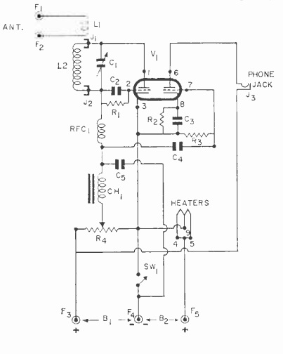
The radio function was added by use of something found in almost every home, “a small table-model radio set of the ac-dc type that has been set aside because of a broken cabinet, missing knob, or a minor circuit defect.” Such a radio was squeezed in, with the controls mounted under the phone’s writing desk.

Obtaining the phone was a matter of ordering one from Telephone Repair & Supply Co. of 1760 W. Lunt Ave., Chicago, where it was available for $7 plus postage for the 20 pound instrument. Most such surplus phones came with the crank, but not the magneto, since apparently the phone companies still needed some of those for their rural customers.  The phone will have been in service for fifty years, so the article gave details on how to refinish the wood and metal components.

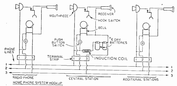
The article next explained how to wire the phone back up. Even without the magneto, the ringer could be made to work by including a button on the side of the phone (where the crank used to be), wired to the bell through an induction coil. Presumably, the phone would ding once when the button was depressed. A three wire circuit (or two wires plus ground) was used to hook the phones together, with one wire for the voice connection and one for the ringer. The wiring diagram is shown here:
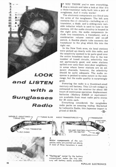
1959RadioTVExp4


1959 One Tube VHF Receiver

1959RadioTVExpSixty years ago, a 1959 issue of Radio-TV Experimenter carried the plans for this one-tube VHF receiver. The superregenerative set covered 27-200 MHz. Since the sunspot cycle was cooperative in 1959, the set pulled in a lot of DX. On the 10 meter amateur band, the author reported hearing hams in Mexico, Cuba, Alaska, and Japan. In addition, he pulled in paging services in California and Puerto Rico, and police stations in South America, all with an indoor wire antenna. With an outdoor beam antenna, he pulled in the audio of BBC television in London.

One half of the 12AT7 tube acted as the sensitive detector, with the other half serving as audio amplifier. Plug-in coils were used for band switching.

1959RadioTVExp2