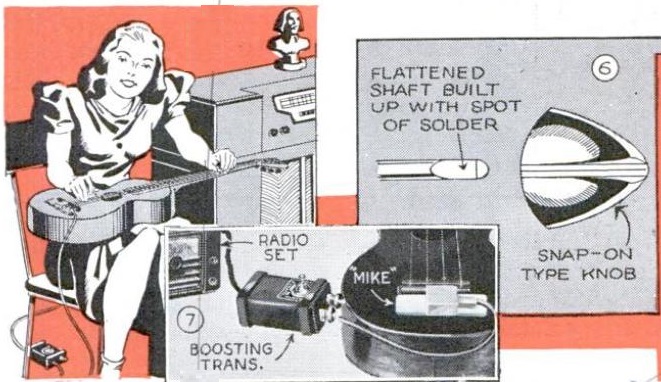
The musician shown here, under the watchful eye of J.S. Bach perched atop her radio, is an early adopter of the electronically amplified guitar. She has a small pickup microphone mounted on the guitar, which is fed into the boosting transformer shown. The output went to the radio’s phono jack, or if it didn’t have one, to the volume control.
The picture to the right, while unrelated, shows a hint that is worth noting. The radio knob had come loose from its shaft. The problem was solved by adding a bit of solder to the shaft to build it up and ensure a tight fit.
The illustration appeared in the April 1940 issue of Popular Mechanics.
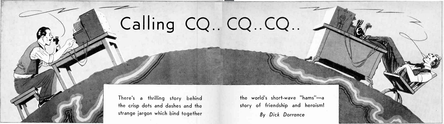
Broadcast listeners 80 years ago, while tuning the shortwave dial of their set, might occasionally have heard the sounds of “that fool kid down the block,” namely a ham radio operator, coming through the speaker of their console set. But this article, in the April 13, 1940, issue of Radio Guide reminds listeners that that fool kid was a member of an “old and honorable clan–a clan which, out of its own altruism and persistence, has helped give us the wonderful marvels of radio which today we take so much for granted.”
The article highlighted both the technical tinkering and “ragchewing” done by hams, who, according to the article, averaged 27 years of age.
The article starts with a story that is familiar, but I suspect at least partly apocryphal. A ham in Alaska was working a ham in New Zealand. The ham in Alaska gave a report of 549x. But suddenly, the “sharp dots and dashes faltered, once, twice, then pieced out falteringly. ‘I feel ill ….” Suddenly, the radio went silent.
The ham in New Zealand put out a distress call, and eventually raised a station on the West Coast of the U.S. He put out a call for Alaska, and soon raised another station in the Alaskan ham’s hometown. That ham raced to the house, dragged the unconscious ham outside from the home where he had been suffering from carbon monoxide poisoning.
No names were given, and the story is almost identical to the one given in the 1939 film Radio Hams, which appears at the bottom of this page. The story recounted in the film took place “some years ago,” and similarly contains few details. It does mention the name of the ham, Clyde De Vinna, and there seems to be some corroboration on his Wikipedia entry, although few details of the incident.
The article does identify another ham, Frank Carter, W2AZ, of East Rockaway, Long Island, who maintained daily contact with the Archbold Expedition in New Guinea. Other stations involved in that communication were K4FAY in Puerto Rico, W6LYY, W4DLH, and K6OQE in Hawaii. The magazine recounted a story of W2AZ getting an urgent call from a station in Colobmia looking for information on his children who were ill in a New York hospital.
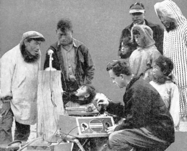
Shown here operating an RCA recorder is Father Bernard R. Hubbard, “the Glacier Priest.” Hubbard was an American Jesuit Priest, ordained in Austria in 1923. Upon his return to America, he was a college lecturer in German, geology, and theology. He found, however, that his heart wasn’t completely in academia. He therefore undertook regular expeditions to Alaska to study geology and volcanology. By the late 1930s however, his interests turned to anthropology, and he began to study the culture and language of native Alaskans.
He was a compelling lecturer, and at one point was the world’s highest paid member of the lecture circuit, earning up to $2000 per talk. He donated the money to Jesuit missions in Alaska.
He’s shown here on the cover of National Radio News, April-May 1940, recording chants by these native Alaskans.
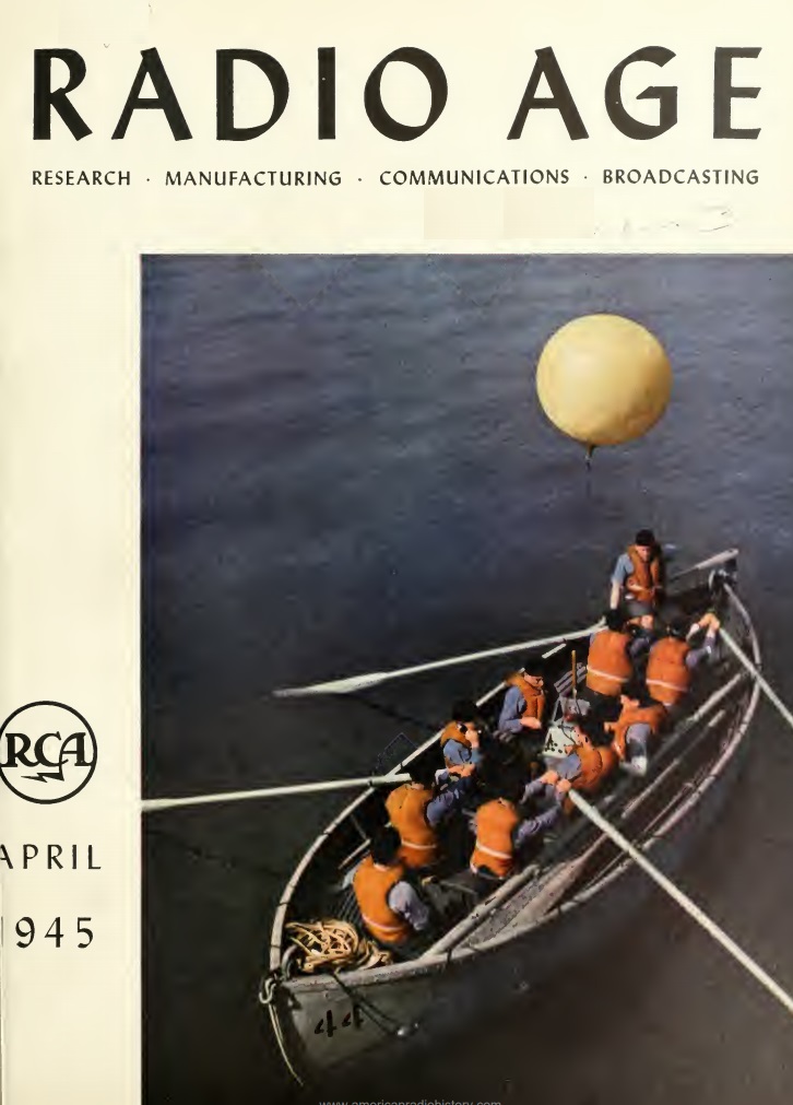
We previously featured the Radiomarine Corporation of America’s model ET-8030 lifeboat radio. While the set was never deployed during the war, it was featured in the April 1945 issue of Radio Age, a quarterly magazine published by RCA. It is featured on the cover of the magazine, being operated by cadets at the U.S. Merchant Marine Academy, Kings Point, N.Y..
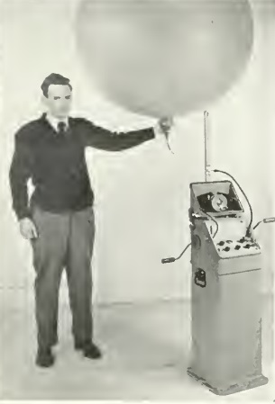
The set, permanently mounted in the lifeboat, operated with a hand crank which provided the power and keyed the transmitter. In the automatic mode, the set would send a long dash and SOS on 500 kHz and 8280 kHz. It could also be switched into the manual mode, which allowed voice transmission, and included a receiver for both 500 kHz and 8100-8600 kHz. The set could be used with an inveted vee antenna mounted to the boat’s mast, but the most prominent feature was a helium balloon which could hoist the antenna to height of 300 feet and keep it there for a week. As a backup, a box kite was also provided.
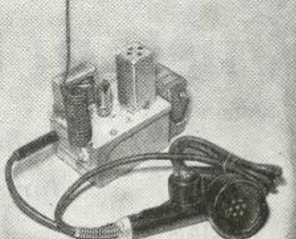
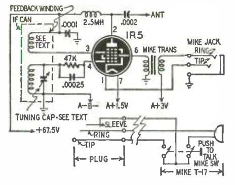
The April 1950 issue of Radio Electronics carried the plans for this one-tube home broadcaster, dubbed the “Carry-Talkly” by author Otto Wooley, W0SGG. The microphone and chassis were easily sourced, since they were both war surplus, a Signal Corps BC-1366 jack box, and the T-17 microphone. The circuit used a 1R5 tube, and an 18-24 inch antenna provided a good signal around the house.
The author’s set was tuned to 550 kHz, although he pointed out that on a receiver with a high-gain IF stage, the broadcaster could be tuned to the intermediate frequency and be picked up regardless of the receiver’s dial position.
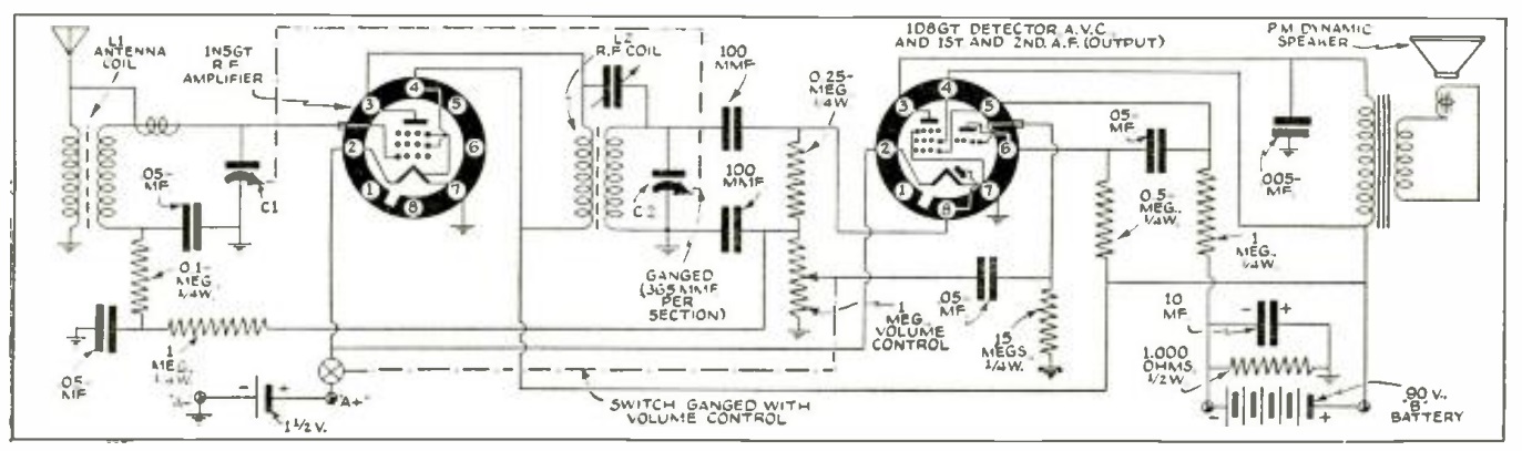
Roger Dickey of Grand Prairie, Texas, had been a radio serviceman since 1933, and had frequent requests from local farmers for a small economical battery operated radio. Even though the farms weren’t electrified, there were a number of strong local stations, including 50,000 watt WFAA only about 10 miles away. The expensive commercial sets on the market were overkill, and Dickey set out to come up with a better set suited to local needs.
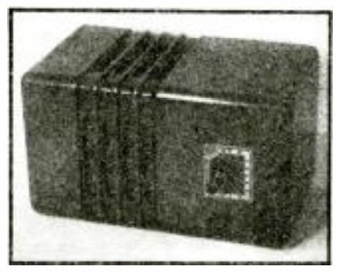
He did so with the two-tube TRF set shown here, which he said performed about as well as a superheterodyne. The set used a 1N5GT as RF amplifier, with a dual tube, a 1D8GT serving as detector, and first and second AF stages. A short antenna pulled in all of the local stations during the day. At night, with the longer antenna, the set pulled in WGN and WMAQ from Chicago, WLW Cincinnati, and WSM Nashville, without any overload from the 50,000 watt station just ten miles down the road.
The design was featured in the April 1940 issue of Radio Craft magazine.
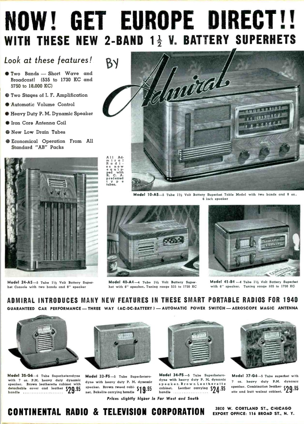
Eighty years ago, this ad showing some of the Admiral line of radios appeared in the April 1940 issue of Radio Retailing. Even rural Americans without household electricity would be able to pull in Europe direct with these battery shortwave sets. The sets all featured 1.5 volt filament tubes, and the combination A-B battery packs were readily available.
The model 10-A5 was a table set that tuned the standard broadcast band (including police calls, since it went as high as 1730 kHz) and 5.75-18 MHz shortwave to hear the war news directly from the capitals of Europe. The model 24-A5 was a comprable console model.
For broadcast only, the model 40-A4 and 41-B4 table sets were shown. The ad also featured four portable sets that could operate from AC, DC, or internal battery. The ad promised guaranteed car performance.
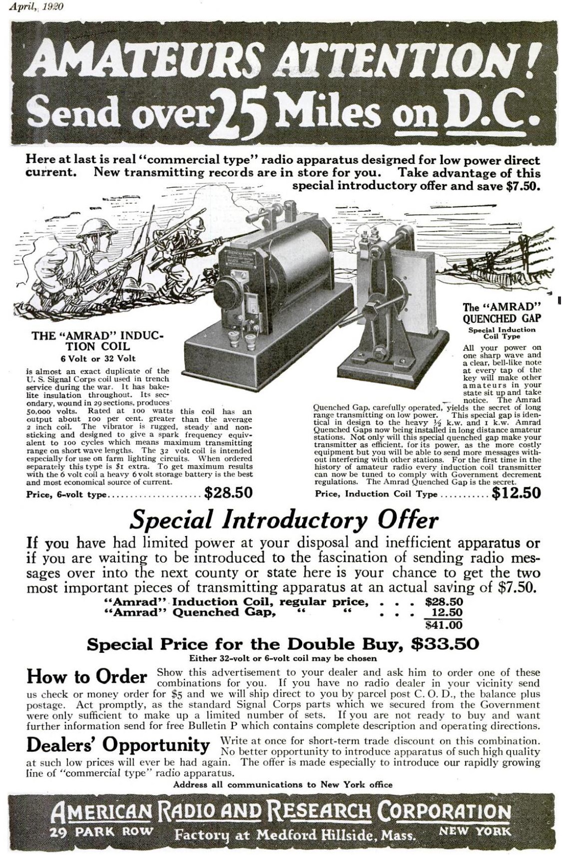
A hundred years ago this month, the April 1920 issue of Popular Science carried this ad for an induction coil and spark gap said to have a range of 25 miles using direct current. The induction coil, which consisted of a vibrator, primary winding, and secondary winding, would produce a high voltage alternating current using a 6 volt storage battery. This was fed to the quenched gap, which produced the spark to be radiated by the antenna. Together, the two components were the heart of the transmitter. The induction coil was also available in a 32 volt version for use on farm lighting circuits of that voltage. This setup was promised to make other amateurs in your state sit up and take notice when your signal showed up in the ether.
The two components were available together for $33.50. It was recommended to buy the set from your local dealer, but if none was available, the American Radio and Research Corporation would send it for five dollars down, with the balance plus postage paid C.O.D.
Since the set used high-quality surplus Signal Corps parts, only a limited number of sets could be made.
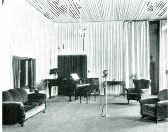
Seventy-five years ago, station CKY in Winnipeg asked its listeners to submit reminiscences of the early days of radio. Many of these were published the the station’s monthly program guide, Manitoba Calling. This one appeared in the April, 1945, issue, which also carried the photo above of the station’s studio in 1928:
This one was sent in by W.J. Cooper of Steep Rock, Manitoba. The magazine noted that his was a familiar name as a loyal listener in the early days of the station.
My experiments in radio go back to the days when it was called wireless telegraphy. I think it was in about 1916 that I got some spark coils and rigged up a spark set. For a detector
I used two carbon blocks filed to a sharp edge. They stood on end and a fine needle was laid across the sharp edges. Our two stations were only a couple of hundred yards apart, but the
junk actually worked.
My next experience came in about 1922 -1923. Radio stations were springing up all over the continent. There were several stations operating in Winnipeg. (2 in 1923). They quit when
CKY took over broadcasting in Manitoba in 1923. My first set was almost entirely home -made, with the exception of the tube, socket, phones, and batteries. It took up all the space in a cabinet almost as big as a suitcase. The hook-up was a spider-web 3 circuit, single tube. After many nights’ efforts it was made to work. The first reception heard over it was the voice
of the announcer (now editor of Manitoba Calling). He closed by saying “goodbye everybody” and by blowing the call letters CKY on a whistle….
One of the big drawbacks of the early radio sets was that there were too many controls for anyone but the builder to know how to operate. One of the well known super-heterodyne sets had about 50 knobs, dials, verniers, jacks, switches and a couple of meters . . . Hardly anyone but the demonstrators could operate them. However, with the coming of sets with fewer controls, business soon picked up…. CKY was responsible for many pioneer achievements in Canadian broadcasting. Programmes were picked up by a listener’s receiving set in Winnipeg. (Actually two sets, one in Fort Rouge and one on Atlantic Ave., operated by Manitoba Telephone System officials). One night they broadcast the Night Hawks programme from WDAF in Kansas City.
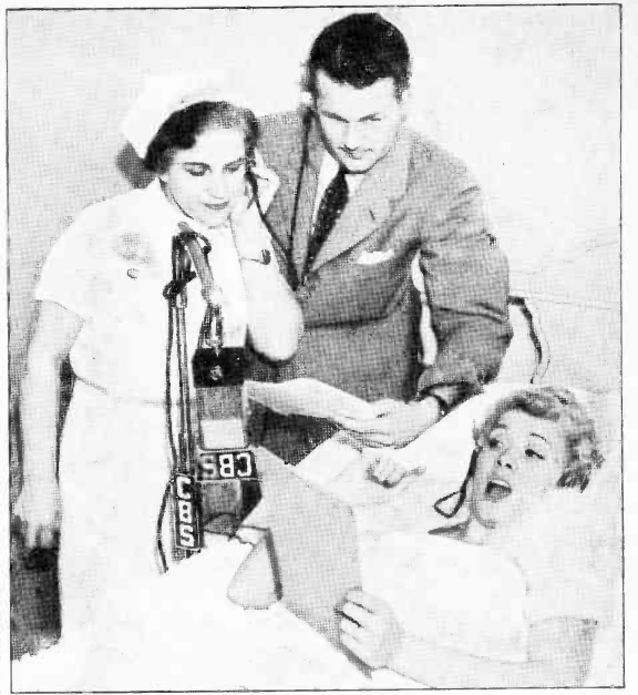
In radio, the show must go on. And that’s so even if the leading lady is in the hospital. Shown here is Penny Singleton, playing the role of Mrs. Bumstead in the Blondie radio series. She was involved in an auto accident that resulted in two broken ribs. But from her hospital bed, she’s reading her lines.
The photo appeared 80 year ago today in the April 13, 1940, issue of Radio Guide.

 The musician shown here, under the watchful eye of J.S. Bach perched atop her radio, is an early adopter of the electronically amplified guitar. She has a small pickup microphone mounted on the guitar, which is fed into the boosting transformer shown. The output went to the radio’s phono jack, or if it didn’t have one, to the volume control.