This image could be mistaken for the studio of a small radio station, but it’s actual the public address console of a wartime industrial plant. Specifically, it’s the console of the RCA Plant Broadcasting System. It appeared in the August 1945 issue of Radio Service Dealer, as part of an article penned by the manager of RCA’s Music Library Service. The article is one of a series giving dealers ideas on how to promote the P-A business, and focused on providing music in the industrial environment.
Plant managers learned that by piping in the right mix of music, they would increase productivity and worker morale. Such sound systems were suitable for industrial plants, as well as office areas devoted to stenographic and clerical work. Business offices such as banks and insurance companies could play music both for workers and customers. And in hospitals, hotels, and stores, music could be piped in over sound systems.
RCA had the musical programming down to a science, and had packages of records available for sale to companies. Musical selections were broken down into four categories.
First of all, there was music for the opening period. These songs would play as workers arrived, and would continue for about fifteen minutes after starting time. These were invariably marches or patriotic tunes, such as “Stars and Stripes Forever,” or the “Washington Post March.” Other possibilities would be upbeat or fast tempo dance selections such as “Pennsylvania Polka.”
About an hour and a half after starting time, and again about an hour and a half before lunch, songs from the “Fatigue” playlist would be played. More songs from this list would be played similar times in the afternoon. Many of these were waltzes, and also popular hits, Latin and Hawaiian tunes, or old time favorites. Some songs on this list included “Green Eyes,” “Star Dust,” and “Begin the Beguine.”
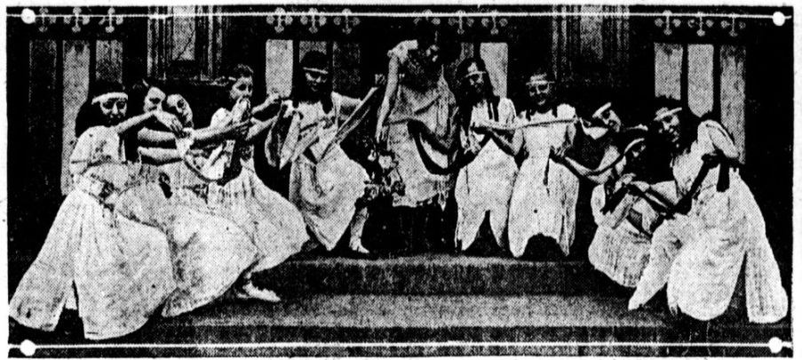
The magazine stressed that the playlists had to be fine tuned to the audience. For example, it noted one small plant where about 75% of the workers were girls between 18 and 23. The music picked for that audience simply wouldn’t work at a plant where most workers were over 35.
RCA’s library also included some records for special occasions, such as Christmas songs and more patriotic tunes.

Workers at Davis & Geck, Inc., Brooklyn, N.Y., pack surgical sutures with the help of music piped in from wall-mounted RCA speakers.
One office employed 600 girls doing monotonous filing duties. Normally, at about 3:00, fatigue would set in, but the author observed those 600 girls instead singing along softly with a popular recording. The office manager was initially skeptical, but experience showed that the vocals did not impede efficiency.
A plant with many Polish or Slavic workers would get more polkas and folk dances. One plant in Trenton employed mostly Italians, and that plant had almost every record Caruso ever made.
Toward this end, one service featured by RCA was a survey that could be given to workers and analyzed at headquarters in Camden, N.J. to come up with a custom record library from the RCA catalog. “The psychological effect of having the personnel feel that the music is theirs, played for them, gives them a personal interest in the project which is otherwise unattainable.” The overall effect was greater efficiency, less absenteeism, and better output.
On the other side of the Atlantic, Britain was also seeing to it that war workers had music. The BBC program Music While You Work was programmed following similar principles. One interesting rule for the BBC program was the banning of the song “Deep in the Heart of Texas,” due to the potential danger of workers taking their hands off their work to perform the hand claps in the chorus.
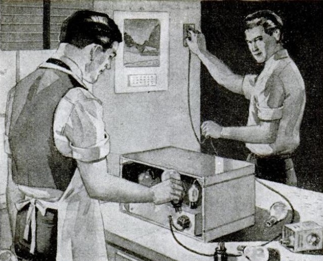 This photo isn’t as sinister as it looks, and nothing untoward is going to happen to the gentleman at the left. The photo is from the August 1945 issue of Popular Mechanics, and these gentlemen are dealing with wartime parts shortages. They’re doing an emergency repair on this set, and need some way to power the filaments of the six-volt tubes. The filament transformer they need is a wartime priority item, so they instead wired the filaments in series and used a 40-watt light bulb as a dropping resistor.