Category Archives: Radio history

1924 Radio Fan

1924ScienceInventionA hundred years ago, this young radio fan is listening to her, well, radio fan. The receiver was constructed into a fan which could be used for cooling. But upon connection to an antenna and ground, programs could be heard over the headphones.

The illustration appeared in the June 1924 issue of Science and Invention, which did point out that if the fan was used for cooling, the detector might get knocked out of place.


ZN414 AM Receiver Chip, 1974

1974JunPEWe previously featured the ZN414 integrated circuit, which contains all of the electronics for an AM receiver in one chip. Fifty years ago, the June 1974 issue of Popular Electronics gave some more ideas for using the chip. The simplest was the receiver for the AM broadcast band shown in the first page of the article. With just a little bit of modification, you could turn it into a receiver for WWV.  The most complex project suggested was a receiver for longwave weather broadcasts.

If you are interested in similar designs, the modern replacement for this chip is the the TA7642, which is readily available on Amazon.

If you want someone else to handle the parts procurement, you can’t go wrong with this Elenco AM radio kit, which uses two IC’s, one for the radio receiver, and one for an audio amp to drive the speaker. (And don’t forget the 9 volt battery and this soldering kit, which contains everything you’ll need to put the kit together.)


Some links on this site are affiliate links, meaning that this site earns a small commission if you make a purchase after using the link.

Bogue Sonic Level Indicator, 1954

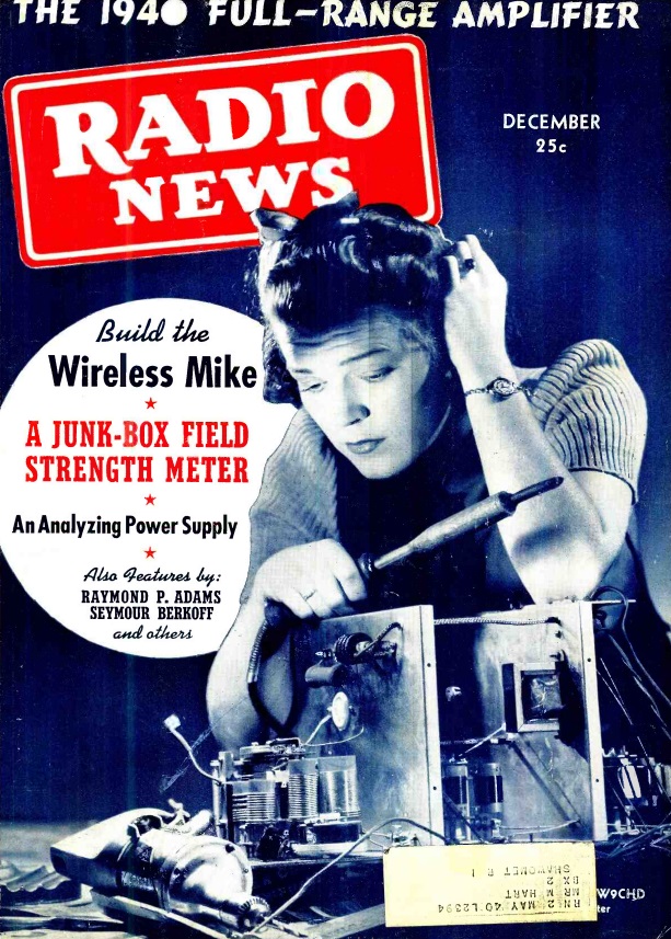
1954JunRadioNewsSeventy years ago, this employee of Bogue Electric Manufacturing Company of Paterson, NJ, is making some finishing adjustments on the model SL-102 sonic liquid level indicator.

The instrument met a long standing industrial need for accurate level gauges in tanks, free from floats and other moving parts. The system was both safe and explosion-proof. The system was able to automatically compensate for differences in pressure and temperature, and was even able to read the interface level of two liquids in the same tank.

The photo appeared on the cover of Radio News, June 1954.


Fahnestock Clip Phone Jack, 1964

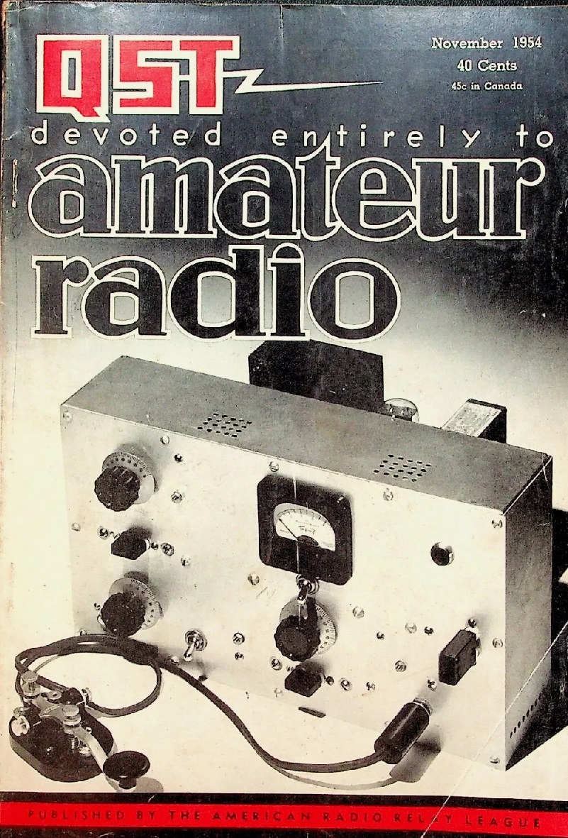
1964JunQSTSixty years ago this month, the June 1964 issue of QST carried this hint (or is it a kink?) sent in to the magazine by Leonard Prescott, WA9CHG. If you needed a phone jack for an experiment you were doing on a breadboard, you could just use two of the venerable Fahnestock clips spaced as needed.


Majestic Model 130 Portable, 1939

1939JunRadioRetailingThis listener was all set for the summer of 1939 with the world’s smallest portable radio, the Majestic Model 130. The three-tube set weighed in at only 3-1/2 pounds, and measured a mere 7 by 5 by 3-1/2 inches.

Also shown are two other Majestic portables. The ad appeared 85 years ago this month in the June 1939 issue of Radio Retailing.


1974 Shortwave Crystal Set

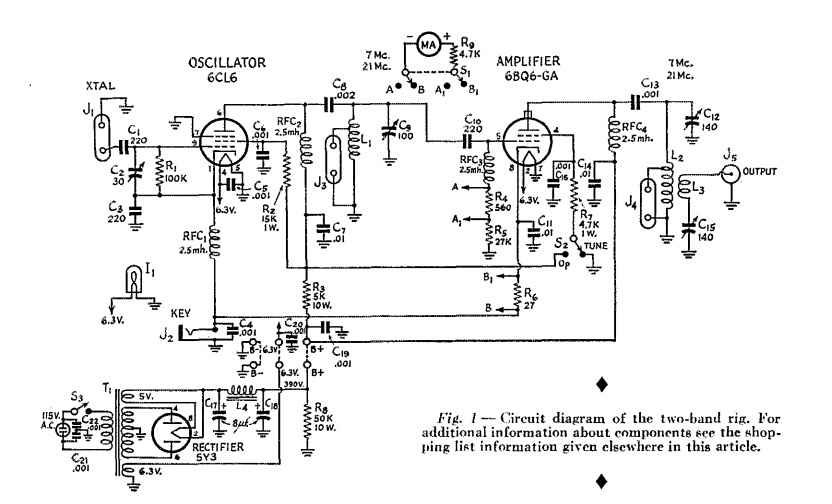
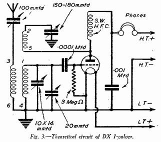
1974JuneRadioConstructorFifty years ago this month, the June 1974 issue of the British magazine Radio Constructor carried the plans for the elusive shortwave crystal set. The author, R.A. Penfold, noted that most published designs covered the medium waves, or (outside of the Americas) the long wave bands. But designs for shortwave sets were relatively scarce, “despite the fact that such designs are capable of far superior results.”

He notes that his design was initially built for its novelty value, but it successfully pulled in many stations, including Berlin, Canada, Hilversum (Holland), Moscow, Poland, Prague, Stockholm, Switzerland, and Vatican Radio. “In short wave terms this is not particularly exceptional, but bearing in mind that a crystal set has no gain, and that the energy which vibrates the diaphragm in the earphone is derived from the power at the transmitter, such results become more interesting.”

This is, indeed, interesting. In his case, the energy from Moscow or Canada was what caused the earphone to vibrate in Britain.

The set tuned 49 through 19 meters, making it useful for the major shortwave broadcast bands. Few parts were required. The 390 kilohm resistor in the circuit is necessary with a crystal earphone, as a DC path is required. This could be omitted with the use of a high impedance magnetic headphone. The coil is about 4 feet of 24 gauge wire on a broom handle. An outside antenna of 50-100 feet was recommended.

The main requirements for operation were said to be practice and patience.

1974JuneRadioConstructor2


Some links on this site are affiliate links, meaning that this site earns a small commission if you make a purchase.

1944 British 3 Tube Receiver

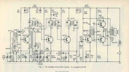
1944JunePracWirThe plans for this attractive and compact receiver were contained in the June 1944 issue of the British magazine Practical Wireless. Even though there was an invasion of Europe going on, the magazine reassured that the parts were available from their advertisers at a low price.

The set gave good reproduction, and the volume was found to be ample for all normal occasions, and it was said to be a good family receiver.

The B+ was supplied by a 120 volt battery, with filament and grid bias batteries also required.

1944JunePracWir2


The Enchanting Tree, 1924

1924JunRadioNews
A hundred years ago, if you wanted to go out in the woods to play a practical joke, you wore a tie, as demonstrated by this picture from the cover of Radio News, June 1924.


1939 Portable Crystal Set

1939JunPM1939JunPM2This woman, like most radio listeners 85 years ago, knew that a good crystal set would pull in local stations with ample volume and excellent tone, as long as an antenna and ground were available. She took advantage of this knowledge and constructed the low-cost (under a dollar) pocket size crystal set with built-in headphone. The antenna and ground leads had clips on the end, so it was an easy matter to clip it to a telephone, as she did here, or even to a metal drain pipe or water pipe.

As long as the building was not of metal construction, this was said to pull in stations from 2-12 miles away. At home with a long outside antenna, receptions of powerful stations 30 miles away was possible.

The design is from the June 1939 issue of Popular Mechanics.


1920s-Era Regen from 1974

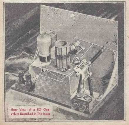
1974ElemElec1Fifty years ago this month, the May 1974 issue of Elementary Electronics showed how to build this receiver, which dated back another fifty years. It was dubbed an “antennaless” one-tube regen, and was said to work well without an outdoor antenna, instead using only a ground connection to a water pipe.

It uses two spiderweb coils, a type 30 tube (although others are possible), a variable capacitor, and only one resistor and capacitor.

I wasn’t able to find the original design, but according to the 1974 article, it was taken from an issue of Radio News from the “early 1920s.”

1974ElemElec2