Category Archives: Radio history

1960 Scout Signaling

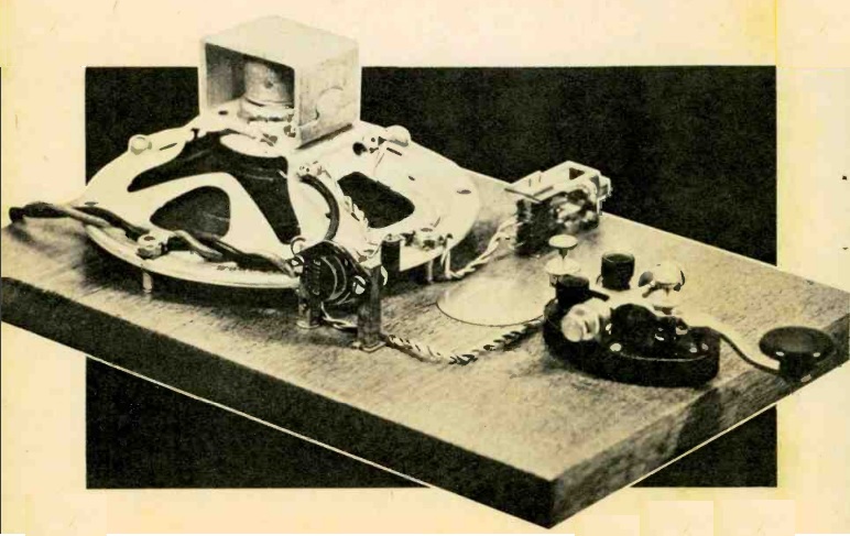
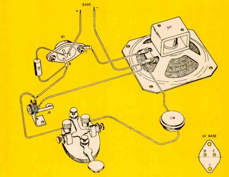
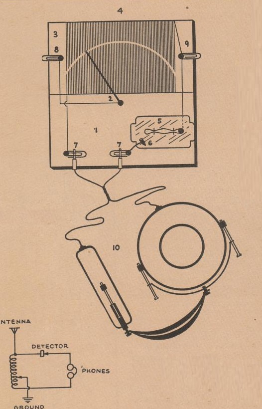
1960OctBL31960OctBL1Sixty years ago this month, the October 1960 issue of Boys’ Life carried two signaling devices. The first was a buzzer-type code practice set. The other, useful for stealthy communications at close range, was this visual signaler, made from a discarded razor blade container. With either one, the scout could get to work on his Morse code, possibly in preparation for Jamboree on the Air, which was announced in the same issue.

1960OctBL2


Wireless on the Boardwalk, 1920

1920OctPSThis trio are listening to music on the Boardwalk, courtesy of this invention by Harold Warren of Asbury, New Jersey. Several miles away, a phonograph record is playing, and they are listening to it on this “small, compact, and relatively inexpensive” receiving set. It combines an “ultra-sensitive receptor” with a loop antenna to pull in the signal, audible enough to be heard above the noises of the boardwalk.

The photo appeared a hundred years ago this month in the October 1920 issue of Popular Science.


1960: First Amateur Moonbounce QSO

1960OctElecWorldThe first amateur radio contact via “moonbounce,” more formally known as EME (Earth-Moon-Earth) took place 60 years ago, as shown in the October 1960 issue of Electronics World.  The U.S. Navy had been successfully communicating since the late 1940s using the moon as a passive reflector, and on July 17, 1960, hams did the same thing, between W6HB in California and W1BU in Massachusetts.  The successful QSO took place on 1296 MHz, with a 1000 watt klystron tube delivering the full legal power to a parabolic antenna.


Start Your Own Recording Business, 1950

1950OctRadioBestSeventy years ago, if you wanted to get into show biz, or at least a small niche thereof, you couldn’t go wrong by starting your own recording business, as shown in this ad for the Home Recording Products Corp., 56 Mill Road, Freeport, NY, in the October 1950 issue of Radio Best magazine.

The possibilities seemed unlimited, and the investment was only $79.95–$10 down, with the balance plus shipping C.O.D.

You would get a professional recording unit (worth $135) capable of cutting both 78 and 33 RPM records, along with carrying case, microphone, mike stand, headphones, and complete instructions. It even came with enough blank records to get back your investment immediately, and additional blanks were available wholesale. With low overhead, you could make recordings for a tiny fraction of the cost of a recording studio.

The possibilities were unlimited. You could connect with a local photographer and make recordings of the children being photographed. Local musicians would want you to cut demo records for them. School bands would want records, and there was potential for a huge volume of business on holidays, as families sent records to loved ones. Even local clergymen would want their sermons recorded.

You would get display cards to put up at local stores to advertise, and you would get sample ads to run in your local newspaper. You could even rent out the unit for use as a public address system.


1960 One Transistor Receiver

1960OctRadioElecSixty years ago this month, the October 1960 issue of Radio Electronics showed how to put together this one-transistor receiver capable of driving an 8 inch speaker. The author reports that the tone quality was excellent and volume surprisingly loud, as long as an efficient outdoor antenna and ground connection are used. The author reported that from 18 miles north of New York City, a 60-foot flattop antenna pulled in 8 stations with fine quality and volume. Uptown, a 45 foot length of wire dropped out the window of a tall apartment building pulled in 10 stations.

The set is nothing more than a crystal set, hooked directly (with no capacitor) to a one-transistor amplifier. The author used a CK721 transistor, but noted that a 2N106, 2N109, or 2N64 would provide good results. He noted, however, that the venerable CK722 didn’t work well in the circuit. A suitable NPN transistor could be substituted, as long as the polarity of both the diode and battery were reversed.

The author noted that increased voltage could be used for increased volume, but it was necessary to closely monitor the current so as not to exceed the transistor’s ratings.

1960OctRadioElec2


Zenith 10-S-590 Radio-Phono Console, 1940

1940Oct12RadioGuideAs we’ve shown before, there was a time when people dressed up to listen to the radio, and as this young woman demonstrates, 80 years ago was one of those times. Shown in the October 12, 1940, issue of Radio Guide, she is listening to her Zenith model 10-S-590 radio-phonograph console. The magazine featured a fashion show of the top-of-the line models available in 1941, and noted that listeners would get plenty for their money in the coming year, taking home a beautiful scientific marvel.

The fact that this woman is dressed to the nines probably means that she’s pulling in a program on the shortwaves, since the 10-tube set (with push buttons and a 12-inch speaker) covered the standard broadcast band and two shortwave bands, 1.8-5 and 6-18 MHz.


1940 British One Tube Shortwave Regen

1940OctPracWirelessThe plans for this simple one-tube wartime regenerative receiver appeared in the British Practical Wireless, October 1940. The author reports that nearly any triode can be used, and he suggests that if more than one is available, they should all be tried to find the best specimen.

The author reported that he was able to pull in many DX transmissions that evaded his friends. He attributed this not only to the sensitivity of the receiver, but also to his patience and possibly good location.

The author used an aluminum chassis, which he acknowledged might not be available. He noted that perforated zinc might be substituted, as long as good ground connections could be made.

1940OctPracWireless2


One Tube Electronic Keyer, 1950

1950OctRadioNews
Seventy years ago this month, the October 1950 issue of Radio News carried the plans for this one-tube electronic keyer. The accompanying article describes the circuit in detail, but the reason for two relays is interesting.  The circuit uses a 117L7 tube, half as a rectifier, with the pentode section serving as the relay circuit.  The length of the dots and dashes is determined by the time constant (R times C) of the resistors and capacitors near the key.  Their voltage is fed to the grid of the tube, which turns the plate circuit on and off.

One of the critical design features is that the next dot or dash doesn’t begin until the previous one, and the space following, are finished. The second relay serves this function, as it doesn’t close until the dot or dash is completed.

The author of the article and designer of the circuit was Donovan V. Geppert, W5KFP, an Assistant Professor of Electronics at the University of Arkansas.  He was the author of the textbook Basic Electron Tubes, which is available online at this link.


1950 One Tube Broadcast Portable

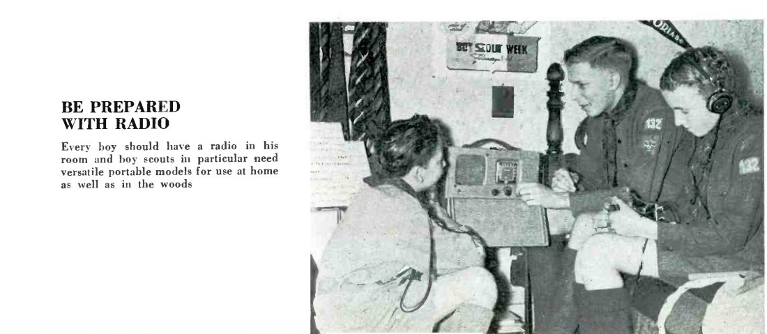
1950OctPMThis young woman is listening to a broadcast program on a “handi-talkie” style radio from the October 1950 issue of Popular Mechanics. The set is a simple one-tube regenerative receiver, with a high-impedance headphone built right into the side of the set’s wooden case. A lead with an alligator clip is used to connected to an expedient antenna. In this case, she is pulling in a station by using the lamp’s metal case as an antenna. A telephone dial stop could also be used, or outdoors, a railing or gutter.

Power is supplied by a flashlight battery for the filament, and a 30 volt hearing aid battery for the B+.

1950OctPM2


1940 Three Tube Broadcast Receiver

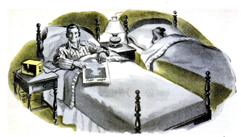
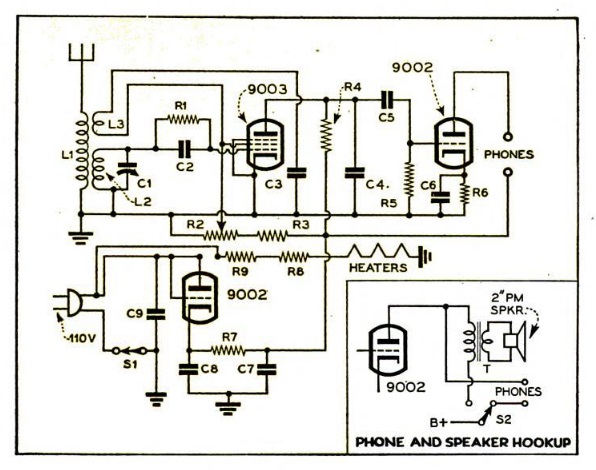
1940OctPS1940OctPS2This gentleman is pulling in a program on a three-tube set he built for only $4.06, following a design from the October 1940 issue of Popular Science.

The chassis for the set was an aluminum cake pan. The article noted that this had the advantage of being able to be cut with a normal pair of scissors. The handsome cabinet was made from scraps of wood from the author’s workshop. The coils for the regenerative set were made “honeycomb” style on cardboard forms. The set covered the broadcast band, but the author noted that by tweaking the size of the coils, it would be possible to pick up stations slightly above and below the standard broadcast range.1940OctPScoils

The efficient circuit provided loudspeaker volume, driving a PM speaker.

1940OctPSschematic