Category Archives: Radio history

1934 Pocket Short Wave Receiver

OneTubePocketSet

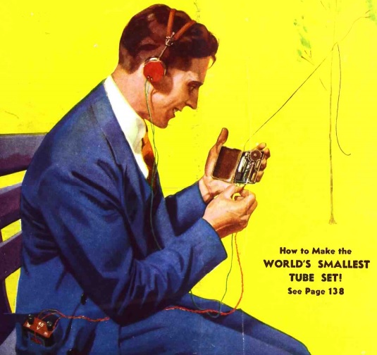
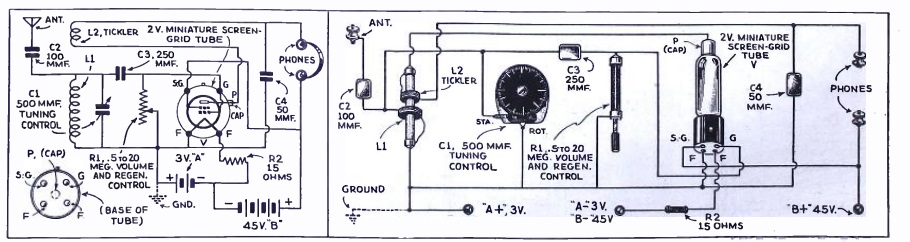
80 Years ago, the cover of the December, 1934, issue of Short Wave Craft featured this pocket portable one-tube superregenerative receiver covering the 49 meter shortwave broadcast band. According to the article, the receiver was able to pull in Europe without an antenna. And when tested with a short antenna in the magazine’s offices in a steel frame building in New York, the set picked up “stations galore.” The article notes that the receiver’s superregenerative circuit had one serious drawback: It radiates a very strong signal. The article therefore recommended that “it be operated only in the less congested areas where there are few short-wave receivers and where the danger of interfering with others is nil.” In other words, this particular circuit probably wouldn’t pass muster under Part 15 of the current FCC rules as an incidental radiator.

The author of the article is George W. Shuart, W2AMN, later W4AMN. He also wrote several articles for QST in the late 1930’s through the 1960’s.  His last contribution to QST appears to be a “Hints and Kinks” item in August 1978 for a CW filter.  A 1946 QST article includes a biography which notes that Shuart had been licensed since 1928, and had written numerous articles for beginners, a result of which was that many amateurs got their start from his articles. It also revealed that Shuart was employed by Hammarlund as its Advertising and Sales Promotion Manager. He was the author of the 1937 Radio Amateur Course
published by the same magazine in which appeared this one-tube radio.

The 1934 article provides two possible solutions for carrying the batteries for this pocket radio. The filaments run on two penlight cells, and the B battery can be as low as 22-1/2 volts. One solution is to make the B battery out of penlight cells bundled together and carried in a pocket. The other alternative is to mount them on a strap “which forms a belt that can be worn around the waist. This is an old stunt used in stage tricks.” A picture of this arrangement is shown in the article, and I would advise against wearing this type of battery while visiting an airport.


Click Here For Today’s Ripley’s Believe It Or Not Cartoon


1924 Monodyne One Tube Radio

Monodyne

This one tube radio is shown in an ad from 90 years ago, from the December 1924 issue of Radio News.  The ad for the National Airphone Corporation features the Monodyne, billed as “one of the most radical advances in Radio engineering. Parts heretofore considered essential are omitted with no loss of efficiency.” One customer reported hearing a broadcast from over a thousand miles away “like talking over the back fence.” It sold for $10, without the tube, headphones, or battery.

I haven’t been able to find any schematic or other details about this little radio. gifarmer.com has some information, including a photo of a nice surviving example. The radio came with two coils, one to cover 150 to 400 meters, and the other to cover 500-1000 meters. That works out to 750 kHz through 2 MHz, and 300 to 600 kHz. Presumably, those band edges were not exact, since there were stations between 400 and 500 meters, such as WLW on 423 meters (710 kHz) and WMAQ on 448 meters (670 kHz).


Click Here For Today’s Ripley’s Believe It Or Not Cartoon


The LFR: 1920’s-1960’s Air Navigation

From the late 1920’s until the 1960’s, an important tool for air navigation was the Low Frequency Radio Range (LFR).

At its peak, there were about 400 LFR beacons in the United States, and many more worldwide. Each station consisted of a transmitter being fed into two directional antennas. One antenna was sending the Morse letter “A”, dot dash. The other antenna was sending the letter “N”, dash dot. The two signals were synchronized so that the two signals alternated. At four directions from the station, the two signals blended to produce a constant tone. If a plane was off this course in one direction, the pilot would hear the “A” start to get stronger. Off course in the other direction, the “N” would get stronger.

Aeronautical charts such as the one shown here would show the letter that would be heard in each of the four quadrants. Here, in the quadrants south and north of the station, the pilot would hear the letter “N”. In the east and west quadrants, he would hear the letter “A”. On the shaded lines, the pilot would hear the continuous signal. These “beams” would be about a half block wide near the station, and as much as several miles wide far from the station. Most air navigation followed routes along these beams. The course a pilot followed would be along airways connecting the stations, and flying cross country would be a game of “connect the dots” as the pilot flew from one station to the other.

Every thirty seconds, the “A-N” signal would be replaced with the call letters of the station, in this case, RL, which would also be transmitted in Morse.

Despite the simplicity of the system, the accuracy was enough to use for instrument landings, and instrument approaches using the LFR beacons were published for many airports.

For the pilot, only a normal radio receiver was required. In later years, more sophisticated receivers were employed, which would show the pilot visually whether he was on the “A” side or the “N” side of the beam. But in most cases, the pilot navigated by listening to the signal in his headphones.

LFR station using Adcock antenna (Wikipedia photo).

LFR station using Adcock antenna (Wikipedia photo).

Most of the stations operated between 190 and 535 kHz, with powers of up to 1500 watts. Early stations used crossed loop antennas, but Adcock antennas (phased verticals) were used in most later stations.

Directly above the station, there was an inverted “cone of silence” where the directional signal disappeared. Even in times of no visibility, the pilot would know that he had passed over the beacon when the signal disappeared.

Starting in the late 1940’s, the LFR began to be replaced by the VHF Omni Range (VOR). While the VOR required a special receiver in the aircraft, it was superior in that it could be used to “fly a beam” in any direction from the VOR station, rather than just the four possible with the LFR.

bc1206

Photo courtesy of Ian O’Toole, VK2ZIO, Kurrajong Radio Museum. Used by permission.

Shown here is a BC-1206C Range Receiver, which would have been installed in the aircraft for the purpose of receiving the beacons. This radio, manufactured by Setchell Carlson, Inc., of St. Paul, Minnesota, is a five-tube superheterodyne.  As you can see from the schematic, it’s not much different from a standard broadcast receiver.

REFERENCES

Click Here For Today’s Ripley’s Believe It Or Not Cartoon



War QRM A Hundred Years Ago

QRM

A hundred years ago today probably marks one of the first times that QRM (radio interference) made the editorial cartoon pages.  This example, from the Richmond Times-Dispatch, December 8, 1914, depicts the interference to U.S. commercial stations from the warships patrolling just outside the U.S. coast.  The signals from the British ships were the primary culprits in causing interference to U.S. stations.


Radio Coverage of Pearl Harbor


imgHandler

USS Shaw at Pearl Harbor. Defense Department Photo.

Contrary to popular belief, the networks never broke into live programming to announcing the attack on Pearl Harbor on December 7, 1941. The first broadcast announcement came at about 2:30 Eastern Time on CBS, during a scheduled newscast.

But you tell me that you’ve heard an announcement breaking into a symphony mid-note, with the words: “We interrupt this program to bring you a special news bulletin. The Japanese have attacked Pearl Harbor, Hawaii by air.” This was actually from a record produced by CBS in 1948. The second sentence came from an actual broadcast later in the day. You can hear the original at this link.

There was apparently no recording made of the first announcement, and there was apparently no interruption of regular programming.

A recording from Minneapolis CBS station WCCO  is available at RadioTapes.com.  While there’s no time stated on the WCCO recording, this was apparently recording during the break in the New York Philharmonic concert, which started at 3:00 Eastern Time.  Therefore, the WCCO recording probably starts at about 3:30 Eastern Time.

References


German and British Amateur Radio Stations on the Air During WW2

Chart showing German amateur frequency bands, 1944. DASD-CQ, September 1944.

Chart showing German amateur frequency bands, 1944. DASD-CQ, September 1944.

It’s widely believed that amateur radio went off the air for the duration of World War II. That was certainly the case in the United States and Canada, as well as most of the warring countries. Some neutral countries remained on the air. For example, Portuguese hams remained on the air, and much of South America was still engaging in amateur radio as usual.


But strangely enough, the major exception was Nazi Germany.  German stations were ordered off the air after commencement of hostilities in September 1939.  But soon thereafter, many stations were granted a special wartime license, known as Kriegsfunkgenehmigung.  QST for April 1940 carried the following announcement sent from Chris Schmelzer, D4BIU:

There seems to be a widespread misunderstanding concerning the activities of German amateur stations to-day. According to a statement made by our government, all sport activities, etc., will be continued during the war to as large an extent as possible. Due to this, amateur stations D4ACF, D4ADF, D4BIU, D4BUF, D4RGF, D4TRV, D4WYF, D4HCF and D4DKN have been relicensed recently. More licenses will follow shortly. The stations are supposed to carry on strictly in the usual manner.

The website of the Foundation for German communication and related technologies contains copies of many wartime issues of DASD-CQ, the journal of  the German national amateur radio society, Deutschen Amateur-Sende-und Empfangs-Dienstes, which continued publication throughout the war.   From recording calls contained in that journal, the author of the web page counts at least 86 active call signs through 1944.  And DC5WW has provided a list (the source of which is not clear) of all licensed stations as of August 1944.  These include a number of stations licensed only for 10 meters.  And a collection of 1943 German QSL cards can be found at the website of Radioclub Braunschweig.  In addition to the hams with transmitting licenses, a larger number of receiving licenses were issued to DASD members.  It appears that the DASD was tasked with approving licenses at this time.  A 1944 letter from DASD president Ernst Sachs to Heinrich Himmler explaining the importance of amateur radio is available online.

So it is clear that there were a significant number of hams on the air from Germany throughout the war.  Many of them, it seems, were using a receiver very similar to the National HRO.  In fact, the tuning condensers were manufactured by National and imported through Portugal.  When the German military believed that they were not up to military specifications, they were given to the DASD for distribution to hams for use in receivers using German tubes.

As shown on the chart above, amateurs were allowed to operate on 20 channels between 3500 and 3600 kHz, as well as 7000-7200, 14000-14400, and 28000-30000 kHz.  (Not surprisingly, the Germans called them kiloHertz rather than kilocycles at the time.)

One can only speculate as to why Nazi Germany allowed its hams to remain on the air when the free world was silent.  The author of this page offers two reasons, both of which seem plausible.  The first was to show the world a sense of normalcy.  Apparently, the idea was for those in the rest of the world to have the impression that life was going on normally.   Or, as the QST article above put it, “all sport activities, etc., will be continued during the war to as large an extent as possible.”

The other reason was more practical.  It was believed that hams and SWL’s could provide valuable propagation information.  Indeed, one source noted that both hams and SWL’s were required to keep duplicate logs and send one copy to the authorities for analysis.

According to that same author, there was apparently no political test for licensees.  There was no special requirement of adherence to Nazi ideology (at least, no more so than required of the general population).  While the original plan to issue licenses was apparently approved by the SS, the actual administration of the program was under the control of the Wehrmacht, whose concerns were presumably more practical than ideological.

Even more surprising is that there were a handful of QSO’s, during the war, between these German stations and British stations!  In 1944, the British government allowed a small number of hand-selected prominent hams back on the air.   Under this program, called “Plan Flypaper” the call signs G7FA through G7FJ were assigned and allowed to operate with 50 watts on 80, 40, 20, and 10 meters. Among these hams was Louis Varney, G5RV, who became G7FJ. The full details of this program, including the operating rules, can be found at the Southgate ARC website.

The participants in this program made numerous contacts with neutral countries, and a handful of contacts with German stations.  They were forbidden from calling German stations, but they were instructed to make the contact if a German station called them.  The purpose of this program was apparently two-fold.  First of all, the idea was to simply make themselves available in case any interesting information was received.  They had instructions, if an enemy station wished to send a message, to relay it to headquarters, and to inform the other station to contact them again the next day for any response.

The other idea was that if any Allied prisoners of war gained access to a transmitter, they would be able to make contact with one of these British stations.  Apparently, neither of these goals was realized.

Here’s another interesting article about amateur radio in Nazi Germany, by Prof. Bruce Campbell KG4CUL:  https://theconversation.com/nazis-pressed-ham-radio-hobbyists-to-serve-the-third-reich-but-surviving-came-at-a-price-90510


Click Here For Today’s Ripley’s Believe It Or Not Cartoon


1939 Floor Lamp Radio

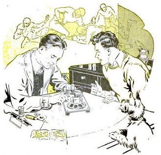
LampRadio1939Seventy-five years ago, Popular Science, December 1939, showed how to make this handy radio to be clamped onto any convenient floor lamp (or simply be used as a standard table radio). It had a myriad of potential uses. “Mounted on a bridge lamp it provides a radio for card games; attached to a floor lamp beside your favorite chair it puts the evening’s programs at your finger tips; and fastened to a standing lamp in your bedroom it serves as a convenient bedside set.”

Frankly, the “floor lamp” feature sounds a bit like an afterthought. The cabinet is hinged and includes cutouts to go around the lamp. A decorative band on the lamp, or a hose clamp, keeps the radio from sliding down.

The guts of the radio itself consist of a two-tube circuit consisting of two loctal tubes. A 7A7 serves as the regenerative detector, with the regeneration control used to control the volume. A 32L7 serves as the audio amplifier and rectifier. It’s an AC/DC set, with a 220 ohm resistor used to drop the line voltage to power the filaments. Because it’s run right off the AC line, there is a capacitor between the external antenna and the set, which the diagram reveals would otherwise be connected directly to one side of the line cord. The article contains a stern warning that this condenser “is extremely important, since it eliminates any possibility of blowing out the tubes or burning the primary of the antenna coil (which could start a fire) should the antenna wire or antenna lead accidentally come in contact with a grounded pipe or radiator” or, worse yet, some hapless person who happens to be touching the radiator.

I wonder how many people built such a radio. By this time, nearly every commercial radio sold was a superheterodyne, rather than the sometimes tempramental regenerative circuit used here. But still, a radio such as this one would be a pretty good performer, and quite suitable as a second radio after the big one in the parlor.

According to the 1942 Allied Radio Catalog (the new loctals were not yet shown in the 1939 catalog), the tubes would cost a total of $1.36. The least expensive table radio in the 1939 Allied catalog (a four-tube superhet) was $6.95.  Since most of the other parts could probably be scavenged from a broken radio, building this little two-tube set could represent a bargain for someone wanting to boast two radios in their home.


1944 One Tube VHF Transceiver

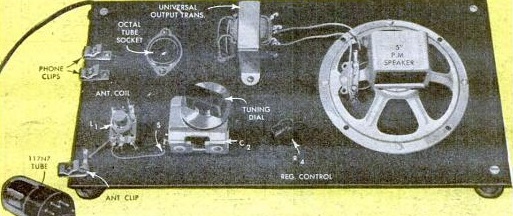
At OneTubeRadio.com, we’e always looking for one tube radios, and seventy years ago, QST carried these circuits for a one-tube AM transceiver for VHF. Since the war had Amateur Radio shut down for the duration, this circuit was designed for WERS on 112 MHz.

The design also took wartime parts shortages into account, since the radio has about the bare number of parts possible to make a functioning transceiver. The author notes that almost any receiving tube can be used, and includes two circuit diagrams, one showing a directly cathode, and one with a separate cathode and filament. A prototype of the unit is shown, built in a cigar box. The antenna, a quarter-wave zepp, plugs into the top of the radio.  (These days, a vertical zepp for VHF is better known as the J-pole.)

The circuit is basically a regenerative receiver, with a carbon microphone controlling current to the cathode. While the modulation percentage is low, the author calls it entirely adequate for short-haul work.

The author recommends a 6J5 tube for the circuit with a cathode, or a 1LE3 or 1G4 for the filament-only circuit, but almost any tube will work. The author does not offer any details as to performance (since he probably wasn’t able to test it on the air during the war). But he notes that “for a transceiver which costs only two dollars or less, as this one does, any attainable range should be satisfactory.”

It’s doubtful whether this simple circuit would meet the current FCC spectral purity requirements for use on the ham bands. After all, even while receiving, the regenerative receiver is radiating. However, if some attention is paid, it’s likely that this circuit would be legal on 49.82 – 49.90 MHz, under sections 15.235 and 15.23 of the FCC rules.

Interestingly, this isn’t the first time that the author of this article has been mentioned at this site. The QST article was written by Gurdon Abell, W2IXK. It appears that he later moved to Connecticut and was licensed as K1EHG after the war.  He passed away in 1999 at the age of 82.  He was mentioned here in an earlier post, and it wouldn’t be incorrect to say that he was the discoverer of meteor scatter communications on VHF.

You can find the original article and a few corrections on the ARRL website. To view these QST articles, you need to be logged in to your ARRL account.


Click Here For Today’s Ripley’s Believe It Or Not Cartoon


Discovery of Meteor Burst Communications, 1944-56

VHF Antenna at FCC Allegan, Michigan, monitoring station, 1944.

VHF Antenna at FCC Allegan, Michigan, monitoring station, 1944.

Seventy years ago, the November 1944 issue of Radio News carried a story of a phenomenon that was baffling radio engineers, and was under investigation by the FCC monitoring station at Allegan, Michigan. The station was reporting strange bursts from distant FM broadcast stations, then operating in the 42-50 MHz band. The FCC station had receivers tuned to the frequencies of distant stations, constantly making a record of the signal strengths as the distant stations came up out of the noise. The signals were bursts of a very short duration in the station’s signal strength. These bursts were rarely of a duration longer than a single spoken word or one or two notes of music.

The bursts have been observed at distances of up to 1400 miles, but were more common at distances of 300-700 miles.

The article was almost certainly describing meteor scatter.  A letter to the editor of QST, November 1946, from Gurdon R. Abell, Jr., W2IXK, seems to be the first reference by a ham to the same phenomenon. He noted hearing bursts of signals during the Perseids meteor showers on 144 MHz, which coincided with bursts from New York HF stations inside his skip zone. He concludes, “if this observation can be relied upon, it means that 144-Mc. signals can be refracted by the stronger meteor trails,” and he seeks further corroborating evidence.

This letter was probably inspired by a January 1946 QST article by Oswald G. Villard, Jr., W6QYT.  Villard detailed how to listen to meteors by monitoring short wave stations on 11, 15, or 18 MHz. A meteor would result in a signal being reflected, but with a doppler shift causing a change in frenquency. The two signals would result in a heterodyne, causing an audible whistle.  Villard followed up with another article in QST for July 1947,  but was still focused on the HF effects of meteors, the highest frequency investigated being 27 MHz.

Two follow-up letters to W2IXK’s appeared in QST in January 1947, from Villard, and also from Bruce Henke, W6TFJ, who noted a similar phenomenon on 10 meters. In April 1953, Villard, along with Allen Peterson, W6POH, wrote an article discussing the possibility of using “meteor scatter” for communications on 15 and 20 meters.

Between 1953 and 1956, VHF operators started to figure out the possibilities of this propagation mode. Many of these are detailed in the World Above 50 Mc column in October 1956.

With digital modes, able to make an entire exchange in less than a second, meteor scatter is now fairly routine. In the 1950’s, it required fast Morse code, and more than a little luck. It’s not impossible, however, with voice modes. From Minnesota, South Dakota is a difficult catch on 10 meters, since it’s well within the skip zone. I have South Dakota confirmed, and I’m pretty certain it’s courtesy of a meteor. During a 10 meter contest, I just happened to have the VFO on the frequency being run by W0SD in Salem, SD, a distance of 225 miles. (If you’re driving I-90 through South Dakota and wonder what those towers are as you pass Salem, now you know.)  He was calling CQ, and he came up out of the noise with a booming signal. I quickly called, we made the exchange, and then he disappeared. He was audible for only a few seconds, and it was dumb luck that I was on his frequency for those seconds. I can’t think of any explanation other than meteor scatter for this contact.

Note:  To view the QST articles linked above, you need to be logged in to your ARRL account.


Click Here For Today’s Ripley’s Believe It Or Not Cartoon


Nazi Weather Station in Labrador

Weather Station Kurt on display at the Canadian War Museum (Wikipedia photo).

Weather Station Kurt on display at the Canadian War Museum (Wikipedia photo).

On October 22, 1943, Germany made its only armed landing on the North American continent of the Second World War. On that day, the U-boat U-537 anchored at the northern end of Labrador and its crew loaded ten cylindrical canisters, each weighing about 220 pounds, onto rubber rafts and then ashore. Together, these canisters constituted an automated weather station, which the Germans had given the code name Weather Station Kurt. The station was one of 26 manufactured by Siemens and deployed around the North Atlantic to give German meteorologists data on weather as it moved across the Atlantic. Other stations had been deployed in Greenland; Bear Island, Norway; Spitsbergen; and Franz Josef Land. Another such station was intended for North America, but the sub carrying it was sunk en route.

One of the canisters contained the meteorological instruments, and one contained a 150-watt  Lorenz 150 FK radio transmitter. (A specimen of this transmitter can be found in LA6NCA’s collection.)  The remaining canisters contained nickel-cadmium batteries to power the system. The system was designed to operate for up to six months, sending a two minute transmission every three hours on 3940 kHz. The data was sent in Morse, which was to be manually transcribed by German radio operators.  Some technical details, diagrams, and wartime photos of the station can be viewed at the links below.

The station was camouflaged, and components were  marked in English with the words “Canadian Meteor Service.” Not only was there no such agency, but Labrador was part of Newfoundland and not Canada.  The station was placed far enough North in the hope, apparently realized, that the Innuit of Labrador would not encounter it.  To confuse anyone who might stumble upon the remote site, empty American cigarette packages were strewn about.  A satellite image of the remote site can be viewed at Google Maps.

The station apparently worked flawlessly, but but was subject to jamming from a source that has never been identified. The Allies apparently never learned of the station’s existence, but It apparently provided weather data for only a few days.

The station was abandoned and not found until 1981. A German researcher working on an unrelated project stumbled onto records of the station in 1977. A retired Siemens engineer who was working on records of the company also stumbled upon references to the station about the same time. He contacted a Canadian Defence historian, who eventually sent a team to the site in 1981. Although some canisters had been disturbed, the station was still there. The station is currently on display at the Canadian War Museum.

References

Read More at Amazon