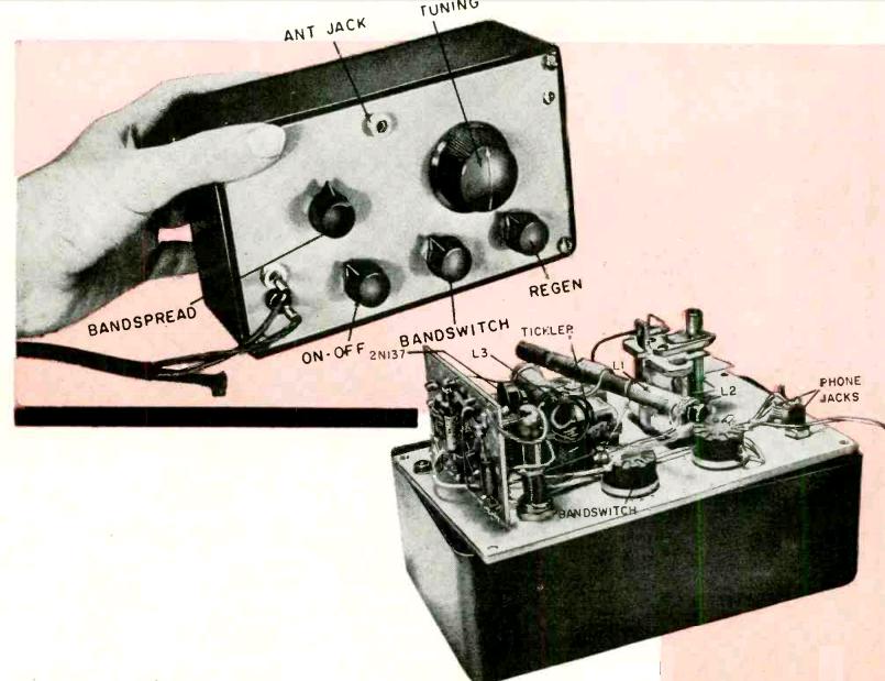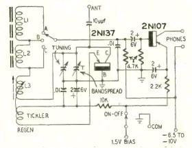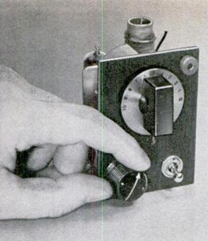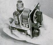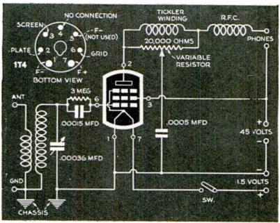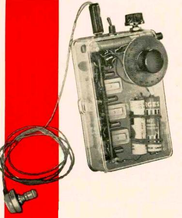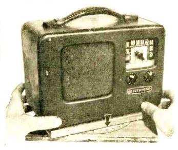
Portable radio mounted on base for direction finding.
Sixty years ago this month, the July 1956 issue of Popular Electronics carried an excellent tutorial on how to use a portable AM radio for direction finding.
Most AM radios, both then and now, are very directional in that there is a “null,” or spot where the signal fades out, on each side of the built-in antenna. You can demonstrate this by tuning to a relatively weak AM station and then slowly rotating the radio. You will find that there are two spots, 180 degrees apart, where the station disappears or becomes very weak. If the radio, like most portables, has an internal loopstick antenna, these are the points where the long narrow antenna is pointing directly at (or away from) the station.
You can use this principle to determine your location. Even with a very cheap radio, you can usually establish your location with astonishing accuracy.
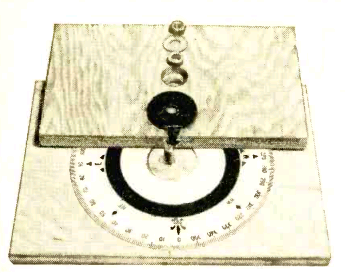
Detail of direction finding mount for portable radio.
The Popular Electronics article shows how to construct a rotating mount for your radio. You strap the radio in place, turn it for the minimum signal, and the pointer on the mount shows the bearing to or from the station in degrees. For example, if the station’s null is at 45 degrees, then you can draw a line on a map over the station with that same angle from north. In other words, in this example, running NE-SW. Your current location is somewhere along that line.
By repeating this process with a second radio station, you will have two lines drawn on the map. The point at which the two lines intersect is your current location, sometimes to astounding accuracy.
The mount shown in Popular Electronics is for a more or less permanent installation in a boat. But this is not necessary. In most portable radios, the antenna is mounted parallel with the outside case, usually with the longest side. Therefore, it is possible simply to use the radio itself as a straightedge: Align the map with the Earth, in other words, place the top of the map toward the north. Then, rotate the radio so that the signal disappears. With the radio at the same angle, place one edge over the station’s location and draw a straight line on the map. Your location is somewhere along this line.
Then, repeat the process with a second station. The point where the two lines come together is your location. To confirm your location, you can repeat the process with a third station. If the three lines come together very close to the same point, then you can be quite certain that the location was accurate. If one of the lines doesn’t seem to agree, then you can repeat the process with a fourth station, and ignore the reading that doesn’t seem to match the others.
With a bit of practice, you can find your location very accurately. In an urban area, by using 3 or 4 local stations, I have identified my location within a hundred yards or so. In a rural area, where the stations might be further away, the accuracy will not be quite as great, but you should be able to locate yourself within a fraction of a mile.
The Popular Electronics article contains instructions on disabling the receiver’s automatic volume control (AVC), because in the case of a strong station, the radio might keep playing at full volume even with the station nulled out. However, it is not necessary to modify the radio. Most stations, unless they are very strong, will show a null even with the AVC functioning. And for those stronger stations, you can compensate by tuning the radio slightly off frequency. For example, if the station you are trying to locate is at 800 and you can’t get a null, you can reduce the signal strength simply by tuning to 810. You’ll still hear the station with the radio properly oriented, but the signal will be weak enough that you will be able to detect the null.
Of course, for this method to work, you need to know the exact transmitter location of the radio stations you plan to use. These often differ from the location of the station’s studio and office. In some cases, they are many miles from the station’s city of license.
Fortunately, in the United States, this information is easy to obtain from the FCC website. You can search for a particular station, for all stations within a state, or all stations within a certain radius of a given location. When you click on the station’s call letters, you will be given the exact latitude and longitude of the transmitter. (Transmitter locations of most AM stations are also shown on aeronautical charts, since pilots still use this method of direction finding.)
Direction finding, even with a very cheap AM radio, can give amazingly accurate results. It is certainly not as convenient as other methods, such as GPS. But in an emergency, it should not be overlooked as a backup method to determine your location. It requires very little equipment (just a radio, map, and pencil). It also requires a bit of practice beforehand, since you need to learn the characteristics of the radio you will use. And it requires knowledge of the location of some local transmitters. But if you can locate those transmitters on your map, you can also locate yourself.
As I mentioned, I’ve been able to determine my own location within a hundred yards by knowing the exact locations of local radio stations. But even without an exact knowledge of their location, I was able to locate myself, at night, within about 30 miles, simply by using the approximate location of strong distant stations. For example, I know that WBBM’s transmitter is in or near Chicago. I know that WSM’s transmitter is in or near Nashville. I know that CFZM’s transmitter is in or near Toronto. Even though I did not know the exact locations of these transmitters, when I used this method at night, I was able to locate myself within about 30 miles. There’s probably little practical application for doing it this way, since it’s unlikely that someone would find themselves not knowing what state they are in. (However, it should be noted that before the invention of accurate chronometers, most mariners wouldn’t know their location that accurately.) But it is still rewarding to know that you can determine your location on Earth with such primitive equipment.
Click Here For Today’s Ripley’s Believe It Or Not Cartoon