A hundred years ago this month, the June 1916 issue of Electrical Experimenter magazine carried the plans for this portable wireless set. The author noted that now that summer was in sight, the progressive radio amateur was making ready for experiments with portable equipment. However, it noted that too many sets were made of extra or discarded equipment, with disappointing results.
The set shown here promised good results with an antenna of 150-200 feet, 30 feet high on each end. The receiver was a crystal set with no power needed, and the transmitter would provide many hours of service with six internal flashlight batteries of 4.5 volts each, wired in parallel. Provision was made for six external large dry cells in series. With this power source, the set would produce a 1/32 inch spark. A test buzzer for setting the detector was separately powered with a 1.5 volt dry cell.
The author noted that the receiver pulled in NAA in Arlington, Virginia, in New York City, a distance of 275 miles, and that longer distances could be covered. The transmitter was capable of getting out about two miles, or even five or ten if an audion detector was used at the other end.
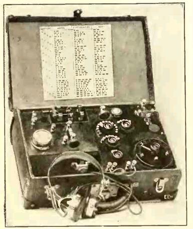
The total weight of the set, mounted in a suitcase, was about 14 pounds, and the total cost was about $15. The article notes that this cost was low enough to bring it within the reach of every wireless club or Boy Scout troop.
The author of the article was Milton B. Sleeper (1896-1963), who later went on to publish a number of magazines, such as High Fidelity and FM/TV. About the time of this article, Sleeper was working for Lee De Forest, and he later became a close associate of Major Edwin Armstrong.
The full schematic of the set is shown below, although it contains one perplexing omission.
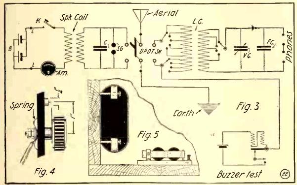
My first reaction when looking at the schematic of the transmitter was to wonder what made the coil spark, since the primary is connected only to DC, meaning that other than the instant when the key was depressed, there would be no voltage on the secondary. The article, however, mentions the spark coil’s vibrator, which is not shown in the schematic. The primary would have an series with it an interrupter, which would rapidly turn the coil on and off, resulting in a square-wave AC current, which would make the transformer work, resulting in a higher voltage on the secondary, sufficient to create a spark. Since a manufactured spark coil was used, the schematic doesn’t show this detail.
A more complete diagram of a similar transmitter, from a 1920 issue of Electronics World shows the internal wiring of the spark coil:
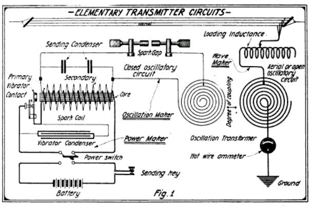
When the key is pressed, the power from the battery energizes the primary of the spark coil. In so doing, the magnetic field pulls open the primary vibrator contact, which kills the power to the primary. With the magnetic field gone, the vibrator contact closes, once again energizing the coil. The wiring is exactly the same as an electrical bell or buzzer, which operates on the same principle. This causes the primary of the coil to repeatedly turn on and off, generating a square wave, which induces a larger voltage in the secondary winding, and that voltage is large enough to generate a spark.
Click Here For Today’s Ripley’s Believe It Or Not Cartoon
