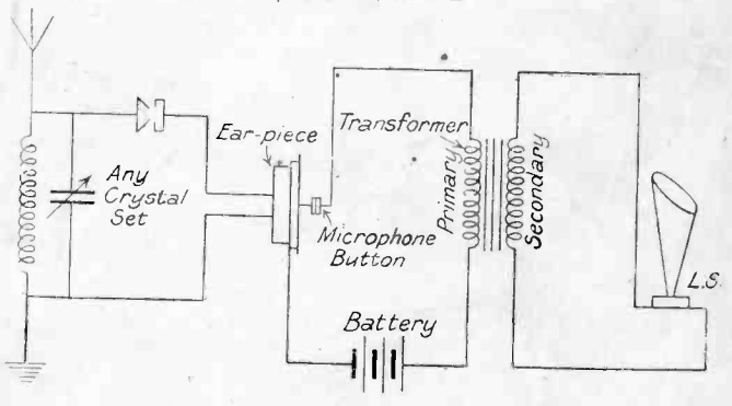
While they were rarely used in radio applications, the diagram here shows how a carbon button microphone amplifier could be used to drive a loudspeaker from a crystal set. This diagram is from 90 years ago, and appeared in the 1927 British Radio Year-Book. The diagram actually appears in the advertisement for a book entitled Successful Crystal and One Valve Circuits by J.H. Watkins, who according to the ad was the wireless correspondent for the Daily Express.
The principle behind the circuit is very simple and almost self-explanatory. The audio from the crystal set or other low-level source is fed to the traditional earphone. A carbon button microphone is in physical contact with the earphone, and produces a stronger AF signal. In this case, this stage is able to drive a loudspeaker.
This idea was rarely used in radio, since a vacuum tube amplifier provided better results and little additional cost. The carbon button amplifier was more commonly used in telephone circuits, where they were the only method of amplification available prior to the vacuum tube. They made long distance telephony possible. They did have the advantage of a smaller size than a vacuum tube, and required less battery power. Therefore, they did remain in use in hearing aids until the advent of the transistor three decades later. You can read more about the carbon button amplifier at this site.
The advantage for the home constructor was probably cost, since driving a speaker this way would not require an expensive vacuum tube. In fact, the carbon button amplifier could probably be constructed at home, which would be impossible in the case of a vacuum tube. Students looking for a very novel science fair project might consider making one, since it would be possible to produce loudspeaker volume with entirely homemade components.
A hundred years ago, magazines devoted to electricity or mechanics were full of ads for learning radio. A large number of these focused on training ship wireless operators. There were other exceptions, but most such schools were located near the sea, in locations such as New York.
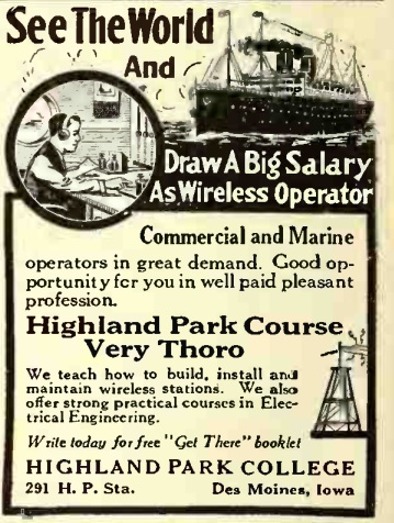
One of the exceptions that caught my eye was this ad for the “very thoro” wireless training program offered by Highland Park College in Des Moines, Iowa, shown here as it appeared in the March 1917 issue of Electrical Experimenter.
The ad promised the opportunity to see the world and draw a big salary as a wireless operator. And the first stop in seeing the world was Des Moines. This is actually not surprising, since the Hawkeye State was a hotbed of early wireless activity, with more than its fair share of amateur operators, and later, broadcast stations and companies involved in radio.
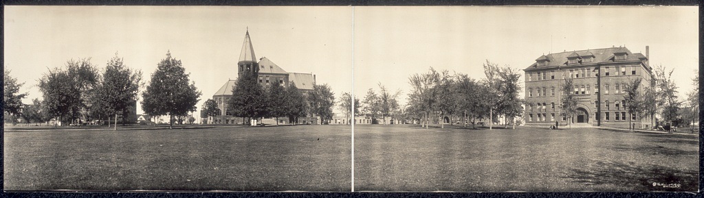
The college offering this course, Highland Park College, is no longer in existence, but had its own colorful history. The school’s Wireless Building, apparently the location where students would be trained to see the world, is pictured here in the school’s 1914 yearbook.
According to the yearbook, the college had a wireless club which had been organized in April 1913, and had a complete sending and receiving set. The book boasted that the station’s large aerial allowed reception of the Arlington, VA, and Key West, FL, stations on a regular basis.
The college was established in 1889 and operated under that name until 1918. It was apparently independent when founded, and in 1911 was transferred to the Presbyterian church.
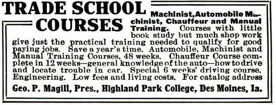
Wireless telegraphy was only one trade that could be acquired at Highland Park College, as shown by this ad in the March 1915 issue of Popular Mechanics. The school also offered courses in machinist, automobile machinist, and chauffeur. The machinist courses ran 48 weeks, whereas the chauffeur course of study could be completed in 12 weeks. The school also offered a “special 6 weeks driving course.”
In 1918, the college was acquired by the Baptist church and renamed Des Moines University. Things went smoothly until 1927 when a fundamentalist wing known as the Baptist Bible Union of North America, the forerunner of the General Association of Regular Baptist Churches, took control. The faculty were required to subscribe to eighteen articles of faith. At that time, the University’s school of pharmacy was apparently the strongest department, and the faculty apparently had doctrinal differences to the point where they refused to sign the eighteen articles of faith. They departed and formed the Des Moines College of Pharmacy in downtown Des Moines. All but two of the pharmacy students left to enroll in the new school.
In addition to the doctrinal requirements imposed on the faculty, the students were facing restrictions. Three girls were disciplined for doing cartwheels during a vaudeville skit.
By 1929, the administration had enough, and fired the entire faculty. A riot broke out, and angry students stormed the administration building during a meeting of the board of trustees. Eggs and rocks were thrown, and the angry students attempted to break down the door of the room where the board members were hiding. Police were called, but the school formally closed down in September 1929.
The buildings sat vacant until 1943, when professional baseball player and aviation pioneer Alfred W. Lawson bought the property and founded the Des Moines University of Lawsonomy, Lawsonomy being billed as “the study of everything.” As might be expected for the study of everything, a degree was not something that could be earned quickly. According to Lawson, the students (men only) would need to study for 30 years to get their degree of Knowledgian.”
Enrollment peaked at a hundred students, but dwindled to 20 when the school closed in 1954 (presumably, with none of the students earning the coveted Knowledgian degree).
The property was sold, two weeks before Lawson’s death, and became the site of the Park Fair Shopping Mall.
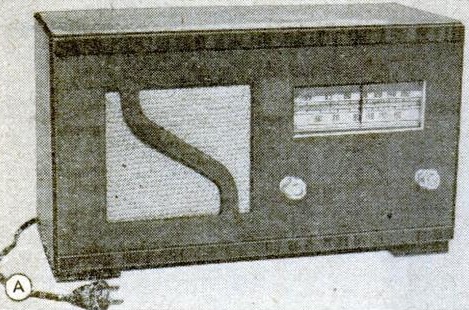
For many years, the March issue of Popular Mechanics had the tradition of carrying the plans for a radio receiver billed the “Little Giant.” A few weeks ago, we featured the 1942 version, and today we offer the version shown 70 years ago in the March 1947 issue.
The circuit diagram for the 1947 version will look very familiar with those who’ve dug into postwar AM radios, since it’s the classic “All American Five” circuit employed for many years by most radio manufacturers. This one has the familiar complement of octal tubes: 12SA7GT, 12SK7GT, 12SQ7GT, 50L6GT, and 35Z5GT. This is also known as an “AC/DC” set, since it could run off either AC or DC 115 volt household current. It’s transformerless, since it rectifies the line cord for the B+ voltage, and wires all of the filaments in series to run directly off the line current.
This circuit does have one interesting postwar twist. Variable condensers were still in short supply, so it uses permeability tuning. Instead of a variable condenser and fixed coil, it uses a fixed condenser and variable coil. The inductance is varied by moving a plastic molded iron core in and out of the coils.
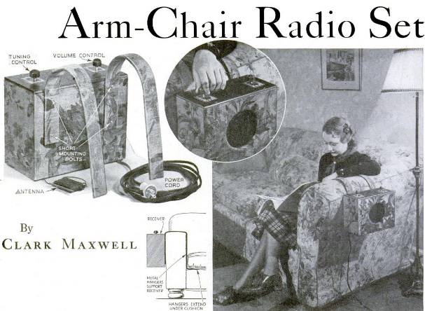
Eighty years ago this month, the March 1937 issue of Popular Science showed how to put together this receiver, which undoubtedly provided armchair copy of local broadcast stations. The author, Clark Maxwell, (not to be confused with James Clerk Maxwell of Maxwell’s Equations fame) explained that he had tried for several years to find a convenient but inconspicuous place for the radio in his living room. He decided to solve the problem once and for all by designing this set to hang on the arm of his favorite reading chair.
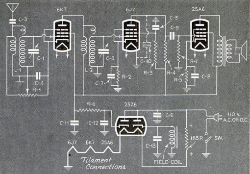
He billed the set as the “Arm-Chair Five,” due to the fact that it had five tubes inside. The radio itself consisted of three tubes, since one served as the rectifier. The fifth “tube” was actually a ballast to drop the voltage of the filament chain.
The circuit was a TRF, with one 6K7 serving as RF amplifier. A 6J7 and 25A6 served as audio amplifiers to drive a speaker.
The author used the set with a 25 foot indoor antenna, although he noted that an outdoor antenna could be used.
Since the chassis was “hot,” he stressed that under no circumstances should an external ground be used. The set was encased in a wooden box covered with fabric to match the chair.
A century ago, cops knew Morse Code, as shown by these New York City police officers appearing in the March 1917 issue of Popular Mechanics.
According to the accompanying article, instruction in wireless telegraphy was being given to the officers, and a wireless apparatus had been set up at headquarters. That station worked in conjunction with other stations around the harbor, and also with a number of private wireless stations that had been placed at the service of the police for emergency work.
Motorcycle couriers would carry messages from the wireless stations to district and precinct offices. At press time, the department had eight certified wireless operators, and sixteen more were under instruction.
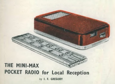
Sixty years ago, it was clear that the transistor was here to stay, and virtually all of the magazines for electronic hobbyists were filling up with construction articles featuring solid-state circuits. More often that not, the project was a transistor radio of some sort. This British example appeared in the March 1957 issue of Radio Constructor magazine.
This set was billed for local reception, but it made up for any lack of sensitivity in the fact that it would provide “loudspeaker” volume. In this case, the speaker was actually originally intended as a headphone element, but the set would put out 40 mW of audio, more than enough to listen to the set without any difficulty.
The set was constructed in a sandwich box cut to size. The author noted that the dimensions given in the construction article were intended for one particular brand of box. So if you want to recreate this set exactly, you’ll need to track down a British “Elevenses Pack” sandwich box. The circuit inside the sandwich box consisted of a diode detector followed by four stages of audio amplification. The set had a built-in loopstick antenna, and would presumably pull in those local stations without an external antenna or ground connection.
The author noted that the industry wasn’t quite ready to supply experimenters with components to construct a small superheterodyne receiver. Small IF transformers were available, but none of them were in the subminiature category. Transistors suitable for medium wave were hitting the market in the U.K., but the small transformers needed for a superhet weren’t yet available “comparable to those available in the States.” But this crystal set with lots of audio amplification would serve the purpose for pulling in the strong local signals, and the hobbyists who built it were undoubtedly the first on their block to own a transistor radio.
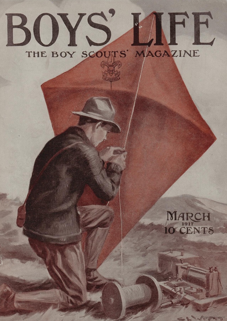
A hundred years ago this month, the March 1917 issue of Boys’ Life magazine featured this illustration of a Scout preparing to send his wireless aerial aloft by means of a kite.
The title of the design is “His Kite Wireless,” by prolific illustrator Charles L. Wrenn (1880-1952).
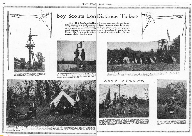
The magazine also carried a two-page photo spread of Boy Scouts as long distance talkers, whether it be by semaphore, telegraph, or wireless. At the time, varying levels of skill in each were required for Second Class, First Class, and the Signalling Merit Badge.
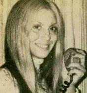
Most red blooded young amateur radio operators in the 1970’s were quite opposed and appalled by the shenanigans taking place on the CB airwaves. On the other hand, most young male amateur radio operators were quite intrigued by the CB column appearing in Elementary Electronics magazine, “Kathi’s CB Carousel,” authored by Kathi Martin, KGK3916. Undoubtedly, most of them probably wondered what a nice girl like Kathi was doing in a place like eleven meters. (We previously wrote about her in an earlier post.)
Kathi Martin, 1975.
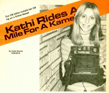
But she seemed to enjoy the CB lifestyle, and who were we to judge. So we read with interest her articles, such as the one appearing 40 years ago in the March-April 1977 issue, reviewing the latest in anti-theft devices, the Kriket Kamel, Model KC-3085, from the Acoustic Fiber Sound Systems company. It was a “hump mount” (hence the camel moniker) for safely mounting a CB radio on the transmission hump of a vehicle.
Kathi begins by noting that the confounded transmission hump on the floor of the car was about the most useless thing in the world. But thanks to the Kriket Kamel, it made the perfect place to mount the CB. The whole radio could be removed without a trace. Without any tell-tale signs of a CB radio in the car, a thief wouldn’t take a chance by breaking into the trunk and rummaging around for one.
She suggested that to complete the CB-free illusion, there were two options for the antenna. First, you could use a combination CB-AM-FM antenna. Since it looked just like a regular broadcast antenna, the thief wouldn’t have a clue that the car was owned by a CB’er with valuable equipment. Another option would be a trunk mount that could be removed completely to inside the trunk.
An added bonus was that this mounting position provided improved sound, since the Kamel also included a speaker, and the transmission hump allowed it to be mounted perfectly for good car-filling audio.
Kathi noted that she wasn’t “one of those helpless type females,” but since an eager male friend was hanging around, she let him do the installation job for her. “I figure it does no harm to let the boys demonstrate how clever they can be too–at least once in a while!” The whole operation required just a few minutes to attach two bolts. The power cord was connected to a cigarette lighter plug, which didn’t even require soldering, since Kathi was partial to crimp-on connectors.
To take the radio out of the car and outwit the thieves, it was a simple matter of unplugging the power, unscrewing the antenna connection, and putting the entire unit in a safe place.
Due to her relatively common name, attempts to find out more about Kathi Martin on the Internet have largely proven futile. The Editor-in-Chief of Elementary Electronics was Julian Martin, WA2CQL, (also known as Julian M. Sienkiewicz), and it appears that CB Editor Kathi was his daughter. But I haven’t been able to find any more information about her. On the other hand, people Google themselves, and it’s not unlikely that she will eventually be reading this. So I’ll put out a request to her: I suspect you have a lot of fans who wonder what you’ve been up to. So if you’re reading this, please leave a comment below or contact me so that I can get them up to date. If you wish to continue keeping a low profile, I promise to respect that wish and will keep your contact information confidential.
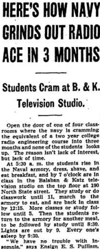
On this day 75 years ago, March 8, 1942, the Chicago Tribune carried this description of the fever pitch at which it was training its radio experts.
It explained how the Navy was cramming a two-year college radio engineering curriculum into three months. Students were housed at the Naval armory where they woke at 5:30, and were in class by 7:00 at the Balaban & Katz television studio at 190 North State Street. The theater company was the licensee of WBKB-TV, located at 190 North State Street, the present location of WLS-TV.
The men were in class until 11:00, at which time they marched back to the armory to eat, and were back in class at 12:15 until classes ended at 5:00. Lights were out at 9:00, and the Ensign in charge of the program reported that there were no problems with insomnia.
In a few months, the men’s duties would include RADAR, so the UHF expertise of the television engineers running the program were ideal for instruction.
The men’s former occupations were diverse, and included electricians, refrigerator servicemen, farmers, and locomotive firemen. Each was given a preliminary scholastic examination by mail, followed by the regular navy physical examination. Even though the scholastic test was tough, the Navy didn’t care whether the students had any formal education.
Many of the men were married, and many had turned down commissions as officers in the Army , instead opting for the rank of naval radioman, second class. They recognized that the training would be invaluable when they returned to civilian life, especially with the prospect of a future in television.
The men were paid $72 per month, with an additional allowance of $34.50 for dependents. It was noted that the men could live on “nothing a week,” with the exception of cigarettes or extras.
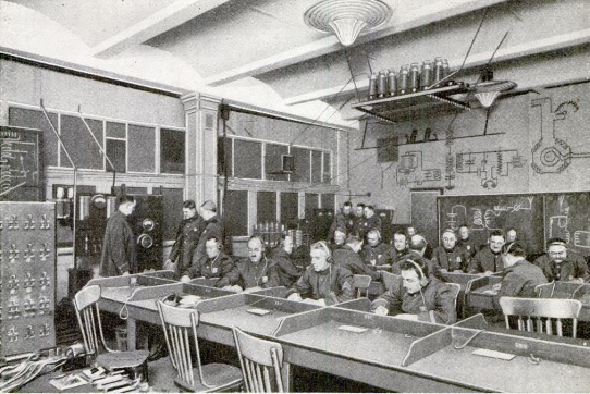
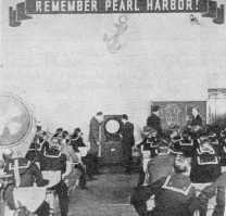
A typical classroom at the school is shown here, courtesy of an article describing this and other Navy radio schools in the November 1942 issue of QST.
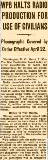
On this day 75 years ago, March 7, 1942, the War Production Board (WPB) ordered that civilian radio production would cease on April 22, as reported in this clipping from the March 8 Chicago Tribune.
As of that date, the entire industry would be on a wartime footing, and the entire industry, with the exception of replacement parts production, would be converted to war production.
A billion dollars worth of war orders were already in the pipeline, and half of that business was to companies making home radio sets. The WPB acknowledged that some unemployment would result as companies switched over to war production, but it was estimated that 95 percent of the conversion would be complete by the end of June.
The board estimated that when the last civilian set rolled off the assembly lines, there would be 60 million sets in operation, with a set in 87% of American homes.
More details of the order can be found at our earlier post.