Category Archives: Radio history

1947 Portable Phono-Radio

1947MarPS

Seventy years ago this month, the March 1947 issue of Popular Science showed how to put together this portable radio phonograph.  It was by no means deluxe, but it was the epitome of portability.  The magazine noted that in most cases, the “portable” terminology meant only that a handle had been slapped onto the cabinet, and the set was still tethered by the need for electrical current.   But in this case, a crank-up phonograph motor and a one-tube battery powered amplifier meant that it was truly portable.

The electronics consisted of a 1D8GT tube powered by two batteries, a 1.5 volt cell for the filaments, and two 67.5 volt batteries providing 135 volts B+, although it noted that it would work with as little as 90 volts.

The magazine noted that the spring motor should be set to 80, which would result in it running at the desired 78 RPM with a record on the platter.

The radio was simply a crystal set with a fixed crystal, which could be switched in place of the phonograph’s pickup cartridge.  While the radio strength was not great, it would serve to pull in local stations, especially with an external antenna and ground of some sort.

1947MarPSschematic


Underground Dutch WW2 Radio Receivers

Another collection of clandestine Dutch radios.

Another collection of clandestine Dutch radios.

Clandestine radio concealed in book.

Clandestine radio concealed in book.

When the Nazis invaded the Netherlands, they didn’t want to deal with the possibility of the Dutch tuning in foreign radio broadcasts. So in the spring of 1942, they simply confiscated all radio receivers.

Undaunted, Dutch radio enthusiasts simply went underground and constructed sets to listen to the BBC and Radio Boston to learn how the war was going. A number of interesting radios were described in the March 1947 issue of Radio Craft, in an article by one Mr. J. Maquerinck, who described sets built by himself and others.

The simplest, or course, was the venerable crystal1947MarRadioCraft3 set, such as the one shown here, constructed by one of the author’s friends. This set pulled in England quite well and was constructed in a wooden box. When the friend wanted to listen, he opened the box, hooked up an antenna and ground, and tuned in the BBC.

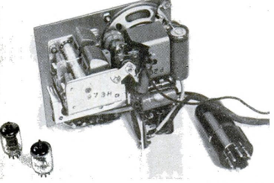
Another friend, who had in his possession a vacuum tube, constructed the simple one-tube set1947MarRadioCraft4 shown here. This friend had no variable capacitor, but the coil wound on an iron core provided adequate selectivity, and was sensitive enough to pull in England.

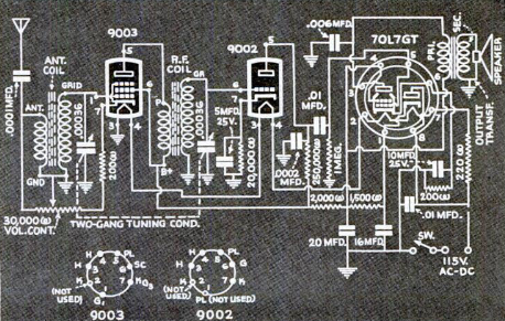
1947MarRadioCraft1The author himself wanted to avoid the complication of an external antenna, which could be seen. He was fortunate enough to own a dual tube, which he was able to use in the circuit shown here as RF amplfier, grid-leak detector, and audio amplifier. To conceal the set, he hollowed out his telephone and built it inside the phone cabinet. His finger served as enough of an antenna to pull in the BBC on 200 kHz. The telephone’s ground connection served as the radio’s ground.

To avoid detection, he had the phone set up so that the dial had to be turned to 7 to power up the radio. As an added precaution, he placed above the radio the sign shown here, meaning “Take care, don’t use. Defective!” He noted that the loss of the telephone wasn’t much of a loss, since it had been out of order most of the time anyway.

1947MarRadioCraft5

This “real radio-telephone” was never discovered. In September 1944, the civilian population of the author’s town was evacuated. When he returned, everything else in the house had been stolen, but the receiver remained.  I guess even Nazis were afraid of messing with the telephone company’s equipment.

The author was evacuated to the town of Aalten, population 10,000. The owner of the home in which the author resided had not previously owned a radio, but the town’s serviceman constructed a regenerative which used plug-in coils, one for 200 kHz and the other for 1000 kHz. The 200 kHz frequency was used to tune in the BBC, and 1000 kHz was the frequency of a station in a part of Holland that had already been liberated.

For another look at clandestine radio receivers used during the war, see our prior post on radios in occupied Guernsey.

Radio concealed in camera, constructed by of , Holland.

Radio concealed in camera, constructed by F.M. Leopold of Eindhoven , Holland.


1942 Popular Mechanics Phono Oscillator

1942MarPM11942MarPM2

Seventy-five years ago this month, the March 1942 issue of Popular Mechanics carried a construction article for this portable phonograph oscillator.  Mounted in the always available cigar box, the one-tube record player used a 117L7-GT tube to produce a signal that could be tuned in on any nearby radio.

The tone arm could be removed when not in use, and plugged in with two phone tip plugs to hold it in place and make the electrical connection.

Since the phono oscillator only required one tube, and didn’t need an expensive speaker or transformer, they were quite popular for playing records for those who already had a radio.

For use right next to the radio, no external antenna was required.  For a bit more range, a short piece of wire could be added.  The coil inside was wound on a one-inch piece of cardboard, and a variable condenser could be tuned to a blank spot on the dial.

1942MarPMschematic


1937 Snow Speaker

1937MarchRadioCraftSnowSpeaker

March is the snowiest month, so there should still be plenty of time to construct the speaker shown here. This speaker was shown 80 years ago in the March, 1937, issue of Radio Craft, and had a number of technical advantages. Since the packed snow has no resonant frequency of its own, the overall frequency characteristics of such a speaker would be excellent. And since the construction material is free for the taking, it allowed a large true exponential curvature.

1937MarchRadioCraftSnowDrillTo construct, simply take a snowball and roll it around until it’s about five feet in diameter. Then, you take your previously prepared “drill,” the exponentially-shaped board, and push it into the snowball untill a cone-shaped hole has been cut. You smooth out the interior by hand, and then place an 8 inch speaker at the back of the snowball (using wax paper or cloth to separate the speaker from the snow).

The magazine suggested that this speaker would be ideal at venues such as skating rinks, hockey games, toboggan slides, or winter carnivals. You can construct a number of them and connect them to a suitable radio or PA amplifier.

Not only will such a snow speaker produce a fine quality of reproduction, but it attracts a great deal of interest.


1942 Popular Mechanics “Little Giant” Receiver

1942MarPMLittleGiantEach March, Popular Mechanics carried plans for a receiver dubbed the “Little Giant,” and the 1942 version is shown here.

With a war going on, this one differed in that it had been stripped of all unnecessary frills and designed for economy.  But the little four tube AC-DC set still offered high grade performance with its superheterodyne circuit, featuring automatic volume control, an electro-dynamic speaker, and vernier tuning.  The set’s open chassis construction also made it easier to build than earlier models.  It tuned from the bottom of the broadcast band to 18 MHz, with three plug-in coils used to change bands.

1942MarPMLittleGiantSchematic


Erec-Tronic Kit, 1957

1957FebRadioElec

Sixty years ago this month, the February 1957 issue of Radio Electronics featured this electronic kit for beginners, the Erec-Tronic. The magazine noted that similar outfits had been around for a long time, but they usually amounted to a wooden breadboard with a few rows of Fahnestock clips. But the Erec-Tronic was the ultimate in educational kits, thanks to the Jiffy-Clip, which could be used horizontally as an alligator clip, as shown on this illustration. But it could also be slid over the pins banana-plug style for quick assembly and disassembly.

The set was touted as a natural for the boy who was just taking an interest in things electronic. It quickly de-mystified schematic diagrams, since the parts could simply be placed right on top of the schematic template to form circuits, such as the code practice oscillator shown here.

The Jiffy connector also removed the necessity for the “mess, dirt, or danger” of solder for the young electronic experimenter. The set shown here sold for about $17, and a transistor version was also available for $13. But these sets were not limited to beginners. Big kits for industry or education were also available with over 300 resistors, 100 capacitors, and scores of sockets and potentiometers, with large basis for assembling advanced circuits. These sold for up to $395.


1937 Popular Mechanics Hurricane Receiver

1937FebPM4Eighty years ago this month, the February 1937 issue of Popular Mechanics carried the plans for this “hurricane receiver.”

Even though it required only about $5 worth of parts to build, the ultracompact set would serve as a rugged portable set which could pull in news during emergencies such as hurricanes. The set, both B+ and filaments, required only 6 volts, and could be run off dry cells for about 12 hours, or from a 6 volt car battery for about 75 hours.

The circuit was a regenerative detector followed by one stage of audio amplification to drive headphones. A 25 foot antenna was recommended, and the set was able to pull in stations up to 500 miles away.

If this set looks familiar, it’s because we’ve featured it here before.  After the plans were published in Popular Mechanics, the set was available as a kit from the  1939 Allied Radio catalog, as we featured in an earlier post.  We’ve also covered an updated 1943 version of the set, which was billed as a wartime emergency blackout set.

1937FebPM5


1947 Two Meter Handie Talkie

1947FebRadioNewsSeventy years ago this month, the February 1947 issue of Radio News carried the plans for this handie talkie for two meters.

The author was C.T. Haist, Jr., W6TWL, and this was the his third version of the set, with earlier ones appearing in the June 1944 and April 1946 issues of QST. Those earlier versions had one bug that still needed to be worked out: Since they used the same oscillator tube for both the transmitter and receiver, the result was that the transmit and receive frequencies were slightly offset. This didn’t pose a problem when working a fixed station, since the other station would probably be using a separate transmitter and receiver. But when two portable sets were used, the result was that each station would need to retune after each transmission, resulting in the two stations chasing one another around the band.

1947FebRadioNews2This set solved the problem by using separate tubes for transmit and receive, with a third tube used in common in both circuits. Transmit-Receive switching was accomplished with a three pole double throw switch.

The compact set had room for a 67-1/2 volt B battery and 2 flashlight batteries running the filaments. The built-in antenna was a repurposed telescoping automobile antenna. The set drew about 15 mA on transmit, meaning that the total input power was about one watt. At 8-10 miles line of sight, the set gave good signal reports. With batteries, it weighed in at about three pounds, and measured 2-1/4 x 2-3/4 x 9-1/4″

1947FebRadioNewsSchematic


Heathkit Single-Banders, 1967

1967FebPE2Fifty years ago this month, Popular Electronics for February 1967 carried this product announcement for the Heathkit Single-Bander transceivers, the HW-12A, HW-22A, and HW-32A, transceivers for the ‘phone portions of the 80, 40, and 20 meter bands.

Priced in kit form at only $104.95, the radios were well received and proved popular for mobile use, along with the accompanying mobile power supply. An earlier version of the sets (without the “A” suffix) had come out three years earlier, and these 1967 models offered more features at a lower price.

A full review for the 20 meter version appeared in the May 1967 issue of 73 Magazine, which can be viewed at this link.


British Women in Wireless, 1942

1942FebWirelessWorldSeventy-five years ago, the War was new for Americans, but Britain had been at war for over two years. As America would also soon discover, labor shortages meant that women would play an increasing role in the workplace and even the military.

The cover of the British magazine Wireless World from February 1942 here shows British women in wireless.  This cover illustration shows women doing practical work on a field set.  The magazine notes that women continued to invade the hitherto predominantly masculine field of radio.  In the illustration below, a group of “girls” are shown practicing their Morse skills.

1942FebWirelessWorld2