Category Archives: Radio history

1938 Mobile Generator

IMG_20180929_231546_690

From the October 1938 issue of Popular Science, this photo is self-explanatory: For a convenient source of electric power, all you need is a generator on the rear bumper, hooked to the drive wheel with a belt and pulley. It can be used in motion, or when stopped, simply by jacking up the rear wheel.


1948 Homemade Transistor

1948OctRadioNewsShown here is a crude but functional homemade transistor from 1948, from the October 1948 issue of Radio News.  While the author had not yet used the fragile device in a working circuit, he did note that he achieved amplification by a factor of up to 50.  The transistor was very unstable at that high amplification, but it did work reliably amplifying by a factor of 15.

The transistor was made of a 1N34 germanium diode carefully broken open.  One lead was kept intact, and the other two contacts were made by making cat whiskers out of filaments of old tubes.

The article cites some 1920s articles where the authors made “amplifying crystals” by a similar means.  By applying the techniques in this article, the advanced student could prepare a science fair project that his or her teacher would probably declare impossible–making a homemade transistor.


Distilling Water

1928OctRadioNewsIf you need some distilled water, it’s usually a pretty easy matter to go to the local supermarket and buy a convenient gallon jug. Or, if you’re willing to pay for the convenience, you can even order it on Amazon.

But it’s also easy to whip up a small batch at home, as shown in this self-explanatory photo from Radio News, October 1928.  The hanging container is filled with cold water, preferably ice water.  It should be as thin as possible.  The spout of the kettle is directed at this container, and the distilled water drips onto a plate below.

The idea was sent in to the magazine by  one C.A. Oldroyd.

If the aspiring young scientist needs distilled water for a science fair project, adding this method to the project will almost guarantee the elusive blue ribbon.


1943 112 MHz Transceiver

1943OctQSTcoverThe cover of the October 1943 issue of QST showed the  transceiver dubbed the “Handy Andy,” a two-tube handie talkie for use on the 112 MHz WERS band. The author notes that strictly speaking, the set is not a transceiver. Even though the same tube is used for both the transmitter and superregenerative receiver, different tank networks are used for each, allowing the frequencies to be adjusted separately. Switching was taken care of with a homemade switch, since both the audio and RF sections needed to be switched over.

B batteries could be used, but the author noted that it was being used with a 130 volt vibrator power supply running from the car battery, which provided about 6.5 watts input power. Range was said to be between a quarter and half mile, which could possibly be extended with larger tubes and higher plate voltage. The RF section could use a 6J5, 6C5, 6F6, or 6V6GT. The audio tube could be a 6F6 or 6V6GT.

1943OctQSTschematic


1958 “Stolen Power” Receiver

1958OctPESixty years ago this month, the October 1968 issue of Popular Electronics carried a project, many variations of which have appeared over the years. It’s a “stolen power” receiver.  It consists of two crystal sets, one to tune in the desired station and another to supply power to the one-stage audio amplifier.

The “power” section is tuned to the strongest local station, which provides a DC voltage of a few hundred milliwatts, enough to power the CK721 transistor audio amplifier. The other crystal set tunes in the station, whose audio is amplified for listening.

To operate, a station is tuned in, and the power section is tuned until maximum volume is achieved. This tuning is then left alone.

According to the article, with a good ground and strong enough local station, the set could come to life with just a metal lamp serving as antenna. For optimum reception, a 50-100 foot outdoor antenna was recommended.

1958OctPEschematic


1938 One Tube Regens

1938OctPSThe gentleman shown here is putting together one of three circuits built around a 6C8G tube from the October 1938 issue of Popular Science.

The first project was a battery powered receiver which used half of the dual triode as regenerative detector, with the other half serving as audio amplifier. Plug-in coils allowed the set to tune both broadcast and shortwave bands.

The second project used half the tube as a rectifier, allowing the set to be used on AC or DC household current.

According to author author, Clark Maxwell (not to be confused with James Clerk Maxwell of Maxwell’s Equations fame), the set was able to pull in several European stations from New York City.

Finally, the magazine showed how the tube could be used as a two-stage audio amplifier.

Battery operated receiver.

Battery operated receiver.

AC-DC Receiver.

AC-DC Receiver.

Audio amplifier.

Audio amplifier.


1948 Car Radio/Battery Charger/Shaver Outlet

1948OctREA staple for many years in electronics magazines was the ad for the Progressive Edu-Kit, a kit which could be re-built in 15 different configurations. A review of the kit and copy of the manual can be found at this link.

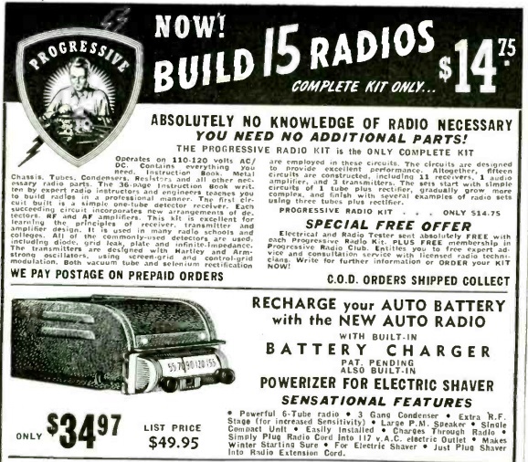
The full-page ad usually appeared on the back cover of the magazine, and as far as I knew, this was the only product ever sold by the company.  But from the ad shown above from the October 1948 issue of Radio Electronics, it appears that the company started out with a more diverse product line.

In addition to the products shown here, the ad from the Progressive Electronics Co., 497 Union Ave., Brooklyn, NY, included a bike radio and car radio.  (The address is now home to the Beer Boutique.)

Shown here is the ad for a combination car radio/battery charger/electric shaver powerizer. In addition to being a 6-tube radio, the set included a battery charger for the car battery. So on cold winter nights, you could plug the car radio into a 117 volt outlet, it would charge the battery all night, and it would “make winter starting sure.”

And if you were running late the next morning, the radio also included an outlet to plug in your electric shaver while you drove to work.


Graphical Method for Parallel Resistors

1943OctQSTThis handy method of determining parallel resistance (or parallel inductance or series capacitance) appeared in QST 75 years ago this month. It was sent in to Hints and Kinks by O.C. Crossland, W9IXV.  All you need is a sheet of lined paper–it doesn’t even need to be graph paper.  You just need to make two vertical lines.

The example shown here computes the value when the two parallel resistors are 6 ohms and 3 ohms.

Today, this would be a simple application of the product over the sum rule.  You would go to the calculator function of your phone and enter (6 x 3) / (6 + 3), and get the answer of 2.

But believe it or not, in 1943, the phones didn’t have built-in calculators.  In fact, they didn’t have calculators at all!  Instead, this graphical method could be used:  You draw a line from 6 on the left scale to the base of the right scale.  Then, draw another line from 3 on the right scale to the base of the left scale.  The point of intersection of the two lines is the answer, 2 ohms.


1922 Crystal Set

1922Lesson7In 1922, this trio demonstrates that diminutive size of a radio set needn’t mean that the set can’t pull in stations. According to the caption, “how small a set may be, and still be operative over short ranges is shown by the little apparatus that lies on the table.”

The photo appears in Lesson 6 of the seven-part “Easy Course in Home Radio” published in 1922. This group undoubtedly made the parts for their set from scratch, as the photo appears in the lesson entitled “How To Make Your Own Parts.”

The young woman at the right appears to be copying code, meaning that she’s probably receiving the weather report from NAA‘s powerful transmitter in Arlington, Virginia.  Undoubtedly, she donned the headphones since she was the best QRQ operator in the group and wanted to make sure the report was accurately transcribed.