Author Archives: clem.law@usa.net

1945 Emerson Postwar Radios: Model 502

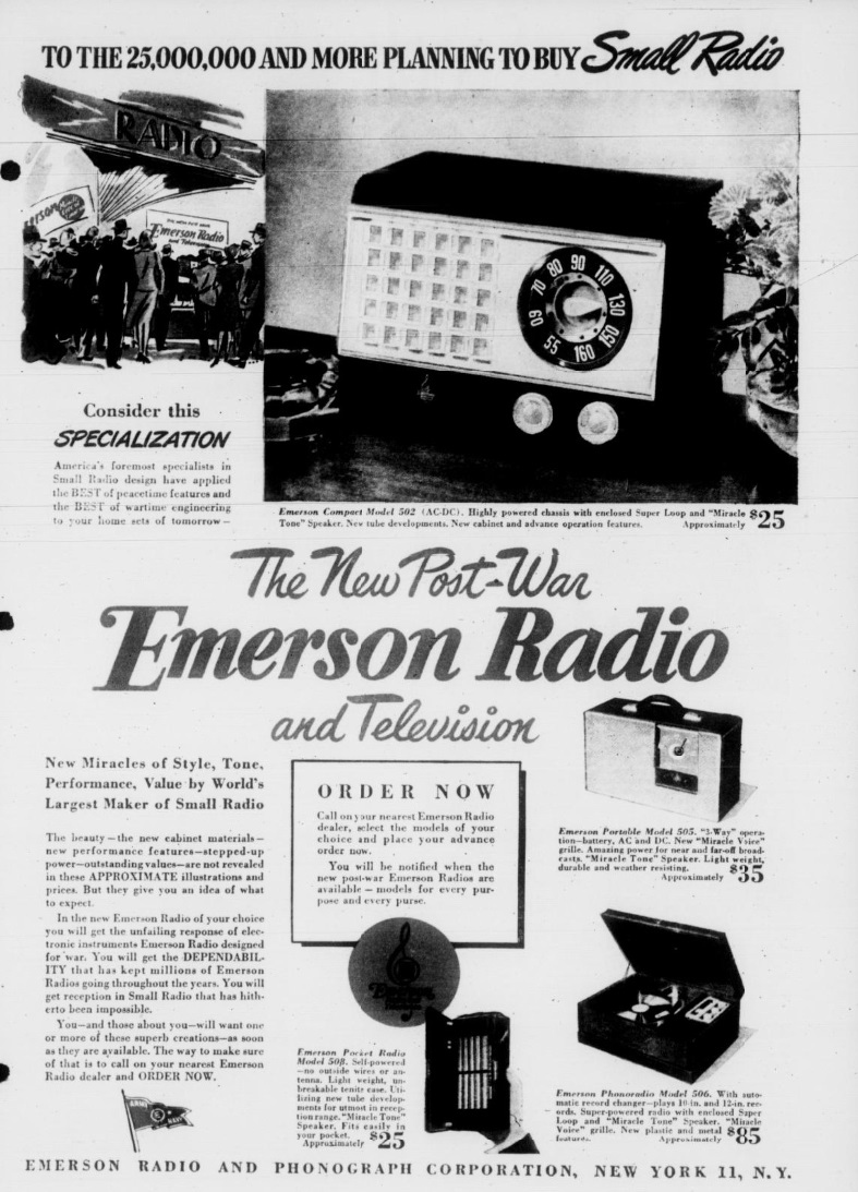
Eighty years ago, production of civilian radios was still banned, but the public and radio manufacturers knew that the end was in sight, and manufacturers were gearing up to meet the pent-up demand. This ad appeared in the Detroit Evening Times, August 26, 1945, and shows what Emerson had planned.

Unlike some similar ads, which were a little bit unclear about what exactly they would be selling, this one hit it pretty close, and featured the 5-tube model shown here. It’s identified in the ad as the model 502.   To make sure you got one of the first, you could go to your local Emerson dealer and place an order.

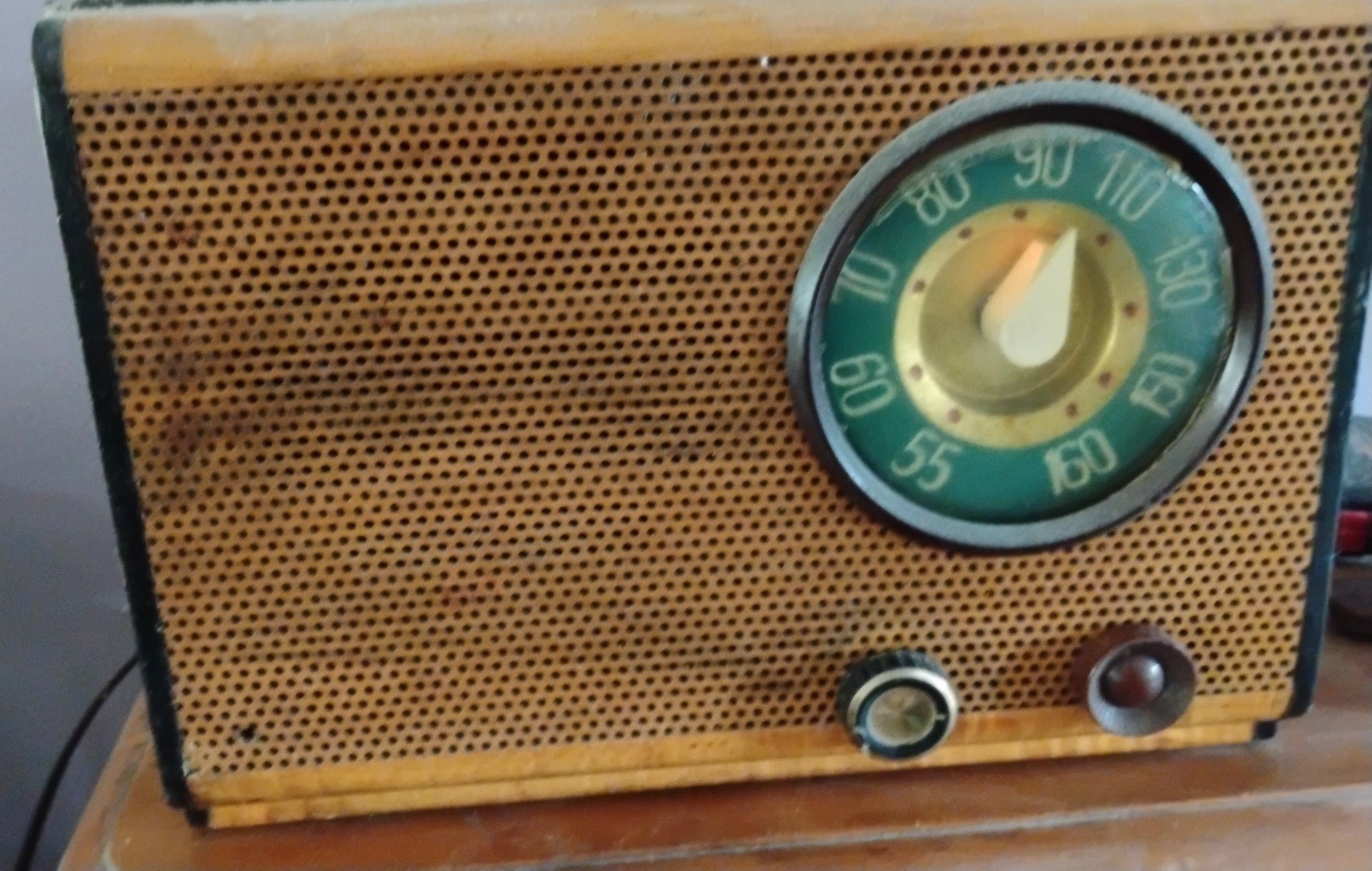
The set was popular.  My family had an Emerson 503 in the kitchen. This was a more or less identical model, but with a wooden case rather than Catalin. When it stopped working, it was given to me to “fix,” although I wound up simply dismantling it. Many years later, I got another example on eBay, and got it working by replacing the capacitors. Mine is shown here.  (If you look carefully, you can see the dial light, as it was playing when I took this picture.  Like most AA5’s, it’s a pretty good receiver.


Teleservice Hobby 3T 29 MHz Transceiver, Italy, 1965

Sixty years ago, this young Italian made made the cover of Radiorama magazine
https://www.worldradiohistory.com/INTERNATIONAL/Radiorama/Radiorama-1965-08.pdf
demonstrating this portable transceiver, Model Hobby 3T, from Teleservice, via B. Galliaria 4, Turin, Italy. The radios did not require a license, but operated on 29.5 MHz with an output power of 5 mW. They had a range of a few hundred meters.


Trailer Radio Shop, Elkhart, IN, 1940

Shown above is the radio service shop of Charles Hurt of Elkhart, Indiana, in 1940, shown here in the August 1940 issue of Service magazine.  He had been in business for a number of years without really making a living, and realized that he had to make some changes. He figured out that to be profitable, he had to make a profit on every single transaction, and he established a bookkeeping system to make sure that happened.

He also realized that there was fierce competition in his area, any one of which were able to press their advantages and force him out of business. The answer was to expand his service area and do it efficiently. Therefore, he purchased the trailer shown here, made it his shop, and adopted the slogan “service at your door.”

Hurt is also shown in this illustration in the December 1940 issue of National Radio News, which notes that the arrangement was also advantageous to the customer, as they avoided charges for pickup and delivery. This item also reveals that for AC power, the trailer was equipped with a dynamotor and storage battery.


1940 Portables

Eighty-five years ago, this couple is relaxing at the beach while they show off some of the latest personable portable radios available on the market. They include models from RCA Victor, Automatic, Emerson, Sonora, Majestic, and Philco. The picture appeared on the cover of Radio Retailing, August 1940.


15 Circuits with 8 Conductors

Sixty years ago this month, the August 1965 issue of Popular Mechanics showed how to use only eight conductors to control 15 different circuits. The trick was using three independent power sources. This way, 5+3 wires could be used to make 5×3 circuits. The magazine noted that the most common application would be for signaling.

Advanced students could use this as a science fair project.  The top components could be switches, and the bottom ones could be lamps.  For another way of making wires do double duty, see our earlier post about a mystery device.


1955 One Tube UHF Transceiver

Shown here, in the August 1955 issue of Radio News, is Robert Richardson, W4UCH, operating a 70 cm handheld radio. He noted that there was little activity above 2 meters, and set out to provide an economical way to get on the UHF band. The cost of each transceiver was only $13, meaning that two could be made for about $25. Range was about a mile over favorable terrain, with distances of up to five miles with an outside dipole antenna. The set was billed as ideal for short-range civil defense work.

On transmit, half of the 12AT7 tube was used as modulator, with the other half as oscillator. On receive, the oscillator functioned as a self-quenching superregenerative receiver.

Tuning was accomplished with a temporary Lecher wire made of two wires nailed to a board. A knife or razor blade was moved along the wires until the receiver quieted. The distance between two such points was half the wavelength.


1940 Battery Converter

The young man in this picture is now close to 100 years old, but in 1940, you can see the look of pride in his face that his dad figured out how to economize on the cost of B batteries for their portable radio. Generally, such radios required two batteries–one, often 1.5 volts, for the filaments, and another one, usually 45-90 volts for the B+.

But here, Dad purchased a converter which allowed him to run the radio from a single 6-volt battery. The power supply, apparently manufactured by Electro Products Co., 549 W. Randolph, Chicago, produced all of the necessary voltages. It could be used, as shown here, with a dry cell battery. Or, it could be used in the car, where an external antenna might also be required.

The picture appeared in the August 1940 issue of Popular Mechanics.


1945 One-Tube Regen

Eighty years ago this month, this schematic for a one-tube regenerative receiver appeared in the August 1945 issue of QST.  It used a 3A5 dual triode, half of which served as detector, with the other half being the AF amplifier.  The use of midget parts allowed the set to be built in a metal case measuring only 4 x 5 x 3 inches.

It appeared in Hints and Kinks, where it had been sent in by Charles Richardson, W8RXY. He reported that two plug-in coils were used to cover 16 through 70 meters. He used it to drive a small speaker, but it could also be used with headphones. He noted that when he was located in England, the set pulled in the States as well as the Orient.


1940 Radio Controlled Airplane

This young woman is now close to 90 years old, but she is shown here, on the cover of QST for August 1940, inspecting a radio controlled aircraft. The accompanying article by Clarence E. Bohnenblust, W9PEP, (probably her father) describes the radio controls. He was approached some time earlier by one C.H. Siegfried, who designed and constructed the gasoline-powered airplane, with a request to design radio control gear. For a transmitter, a 20-watt five meter unit was used. Onboard the aircraft, the superregenerative receiver shown here was used, and could reliably pick up the signal a mile away.

It was determined that four controls were necessary: rudder left and right, elevators up and down, motor speed high or low, and motor shut off. This was accomplished with an elaborate system of cams, operated by a pulsed signal from the transmitter. For pulses, an ordinary telephone dial was used. Each pulse moved the cams one notch, and they were held in place as long as the carrier was received. When the carrier was cut, it reset to a neutral position, ready fpr the next command.

The magazine notes that the airplane was successfully demonstrated at the ARRL Midwest Division Convention in Wichita in April, and was going to be seen again at the ARRL National Convention in Chicago later that year.


Silent TV for the Kids, 1955

These young men have been collecting Social Security for over a decade now, but 70 years ago, they were watching television while their mother and a friend chatted in the same room, undisturbed by the noisy program. You could do it yourself by following the instructions in the August 1955 issue of Popular Mechanics. You installed a remote listening device, similar to the one we recently highlighted, which allowed you to switch off the speaker and route the audio to headphones.

But according to the article, you could “make a big hit with the kids” by installing the headphones inside space helmets, available at toy stores.