Monthly Archives: May 2021

1951 British “Constant Companion”

1951AprRadioConstructorThis utilitarian but handsome receiver graced the cover of the May 1951 issue of the British magazine Radio Constructor. That issue, as well as the June issue, described the circuit and provided details on putting it together. According to the author, the magazine had received numerous requests to design such a set, and those requests asked that the set should be easy to construct, compact, and provide a pleasing symmetrical cabinet.

Those requirements posed a tall order, but with some experimental work, this set, dubbed the “Constant Companion” was the result. The three-tube (including rectifier) circuit tuned the long and medium wave bands, and provided loudspeaker volume with a suitable antenna.

1951AprRadioConstructor2


1951 Crystal Set

1951MayBLSeventy years ago, the May 1951 issue of Boys’ Life carried these plans for “one of the prettiest radios you’ve ever seen.” The chassis was a plastic dinner plate, and the magazine specified that the dish should be yellow, with dashing red fittings. With a good antenna (at least 100 feet) and ground, the set would pull in medium power stations up to 25 miles away.

The coil was wound on a piece of dry wood. As Boys’ Life was sometimes prone to do, they forgot to mention that the enamel insulation would need to be sanded off the wire at the point where the slider contacted it.

If you need help sourcing the parts to recreate this or other crystal set designs, be sure to check out our crystal set parts page.


Homemade Boxes

1921MayPSA hundred years ago this month, the May 1921 issue of Popular Science showed how to make your own boxes. According to the item, it was frequently the case that you needed a box, but didn’t have one of the proper shape and size. With a piece of stout paper, it was possible to make one yourself capable of containing solids, even paper. And if you needed a container for liquids, the same could be done with parafined paper (what we would call wax paper today).

In addition to the practical uses around the house, the younger student looking for a science fair project could compare the qualities of various types of paper in forming boxes.  Of course, if one needs a box with a lid, a second, slightly larger, box could be made to slip snugly over the first.

The idea had been sent in to the magazine by one Peter P. Lembo.


GE LB-530 Portable, 1941

1941MayBLEighty years ago, these young men, probably scouts, are sitting around the campfire pulling in a distant program, with their General Electric Model LB-530 portable.  The five tube (1A7GT 1N5GT 1N5GT 1H5GT 1Q5GT) set operated off an internal lead-acid battery, which could be charged from either a car or 120 volts, either while playing or when turned off. The two volt internal battery lit the filaments directly, and provided the B+ with a vibrator power supply.

We previously featured another ad for the same set. The set retailed for $39.95. This ad appeared in the May 1941 issue of Boys’ Life.


1951 80 Meter Novice Transmitter

1951MayQST11951MayQST3The Novice Class license was first authorized by the FCC effective July 1, 1951. Actually, July 1 was a Sunday, so the first exams probably took place on July 2, with the licenses arriving several weeks thereafter. Novices were allowed to operate initially on CW on 80 meters (3700-3750 kHz) and on the old 11 meter band (26.96-27.23 MHz), as well as both CW and ‘phone on 2 meters (145-147 MHz). The June 1951 issue of QST carried a feature “How To Pass the Novice Examination,” and included the 28 question study guide for the 20 question multiple-choice test.

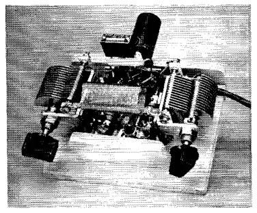
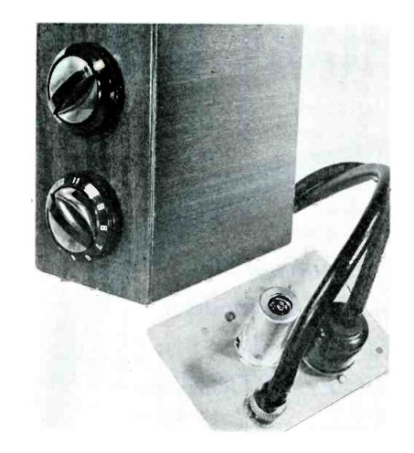
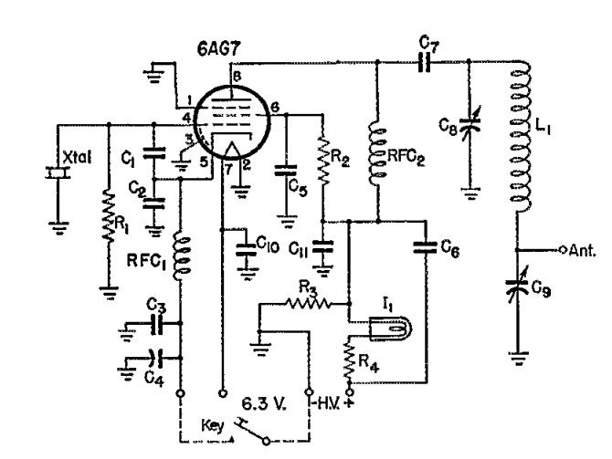
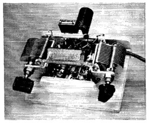
The May and June issues also carried the plans for a simple transmitter for the novice to get on the air. The set was designed by ARRL Technical Editor Don Mix, W1TS, who pointed out that a higher power transmitter, or one on the 11 meter band, might require additional shielding or other precautions to avoid television interference. The simple circuit here, however, was capable of contacts even with an antenna as short as five feet, although longer was, of course, recommended. The retail cost of all of the transmitter components was only $15, and the set required only four hand tools to put together: screwdriver, pliers, hand saw, and soldering iron. The chassis consisted of a board, and the tube socket was mounted horizontally on two metal angle pieces.

1951JuneQST1
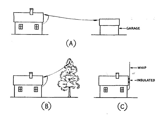
The May issue showed how to put together the transmitter, and the June issue showed an accompanying power supply as well as ideas for an antenna. The author reported that with brief tests from West Hartford, Connecticut, he was able to put stations in Wisconsin and Florida in the log at night, with Maine and Pennsylvania during the day. The set was designed to run to a random wire, and some ideas for the transmitting antenna are shown here. A long outdoor antenna was, of course, recommended, but if necessary, and indoor antenna could be used, and the set would load up into an antenna as short as five feet.
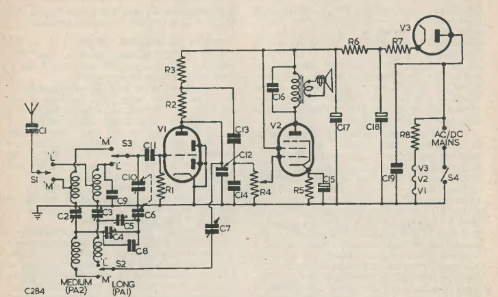
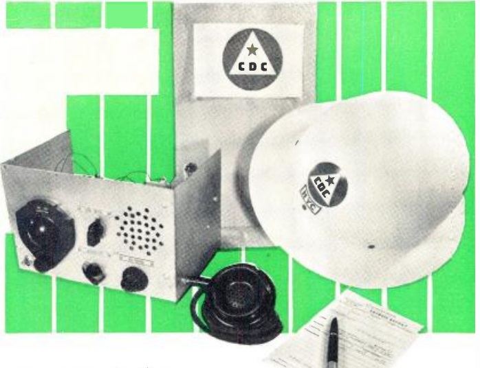
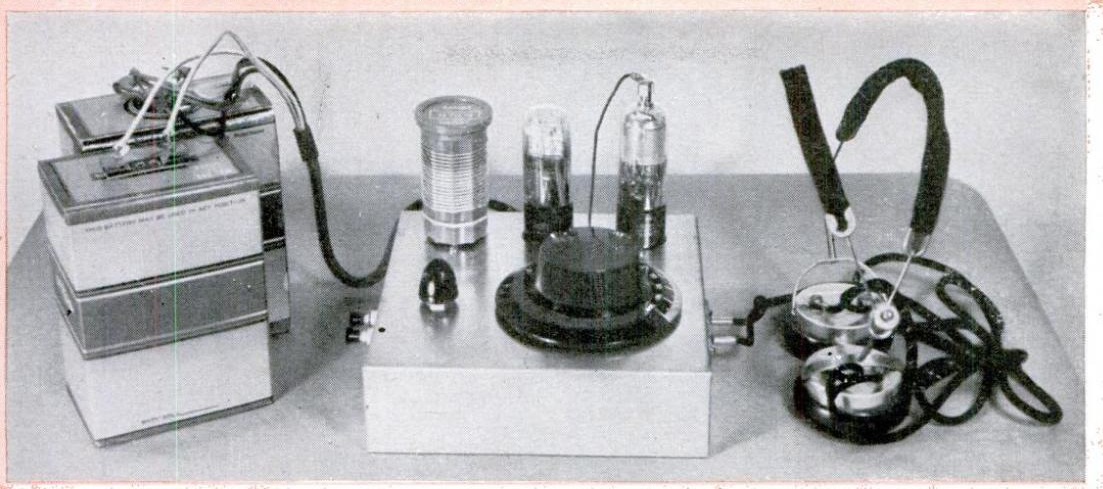
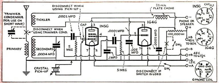
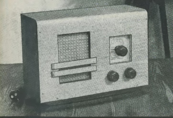


220 MHz Transceiver for CD Use: 1951

1951MayRadioTVNewsSeventy years ago this month, the May 1951 issue of Radio News carried the plans for this 220 MHz transceiver designed for civil defense use. The band was chosen because of it was authorized for use by holders of the newly minted Technician license. With many younger hams being drafted, it was thought that opening up opportunities for Technician class hams would be a way to bring in the operators that were urgently needed for civilian defense operations.

The main design parameter for the set was to provide reliable communications over a 5 mile range. This would be sufficient to cover a small town, or, in the case of a larger city, one police precinct, upon which civil defense operations were often based. Lower bands could be used for inter-city communications, freeing up units such as this for use in local emergencies.

The heart of the circuit was a 955 acorn tube, with more common miniature tubes (6J6, 6J5, and 6V6) rounding up the circuit. The 955 operated as a superregenerative transceiver. The tuned circuit used off the shelf components, but the capacitor required some modification to cover the entire band. If a frequency meter were not available, the magazine noted that in a TV with a 21 MHz IF, the set’s local oscillator would radiate on 225 MHz, allowing calibration of the transceiver. An additional hint in areas with a channel 13 TV signal would be that if the TV station were audible, this meant that the transceiver was tuned too low.

The author reported good signals over a 17-mile path with the set, meaning that for its intended use of 5 miles, the two watt set would likely perform well.

1951MayRadioTVNews2


1941 Sussex, England, SWL Shack

1941MayPracWirEighty years ago, this handsome listening post was located in Sussex, England and was owned by a member of the British Long-Distance Listeners’ Club. Due, undoubtedly, to wartime security needs, the owner was identified only as Member 5490, who had sent the sketch and description for inclusion in the May, 1941, issue of Practical Wireless.

The main receiver was an Eddystone All World Two.  You can read more about that receiver at this link.  The member also had three other homemade receivers as well as amplified speakers. He reported that for light entertainment, he could drive one of the sets with the gramophone pickup and get an output which was quite sufficient for a fair-sized shack. At times when reception was not good, he got quite a bit of fun with home broadcasting, using not only the turntable but the microphone as well.

The member reported that he was waiting for his call up from the Royal Navy as a telegraphist. His normal speed was 32 WPM, but he “managed to take down a couple of pages of French at 42 WPM.” At times, he had managed 53 WPM, but only for one minute.

He reported having 112 QSL cards, covering 83 countries and all continents.


ARRL Fading Tests, 1921

Screen Shot 2021-04-15 at 11.35.14 AM

Don I. Bailey, 9CS.  QST, May 1921.

Don I. Bailey, 9CS. QST, May 1921.

A hundred years ago this month, the May 1921 issue of Popular Mechanics carried a report of the ARRL Fading Tests of 1921.  In collaboration with the U.S. Bureau of Standards, hams took part in a citizen science experiment aimed at understanding the ionosphere.

During the tests, several stations, located in Chicago, Indianapolis, Hartford, New York City, and Washington, sent the letters of the alphabet, forward and backward, while participating stations noted the signal strength. This log was submitted by Don Bailey, 9CS, of Clinton, Iowa.


1951 Remote TV Tuner

1951MayServiceThere was a time when, if you wanted to change the channel on the television, you had to get up and turn the knob on the set. Attempts at overcoming this shortcoming date back to the early days of television. And in 1951, if the entrepreneurial TV serviceman wanted to sell a valuable service to his customers, he could offer a remote tuner such as the one shown here. The May 1951 issue of Service magazine explains everything that needs to be done, and it’s clear that it would be a lot of work.

All of the coils would need to be removed from one unused channel in the set, and replaced with a coaxial cable running to the output of the remote tuner. But it wasn’t quite that simple. The remote tuner would need an antenna input of its own, and it might require a separate preamp. And if the customer wanted to adjust the contrast or volume, that would require additional wiring.

But once done, the customer would be able to change channels from the comfort of his easy chair, a luxury unknown to most people.


1941 Two Tube Regen

1941MayPSThe plans for this unusual looking two-tube receiver appeared in Popular Science 80 years ago this month, May 1941. The controls were mounted on top of the chassis, meaning that the added expense of a front panel was unnecessary.

The set is billed as having two detectors. In reality, a 1N5G tube is used for the detector, with regeneration provide by a 1G4G following it, with that tube’s output being fed back through a tickler coil to the first stage. This made the set very efficient, to the point where it would be able to operate a speaker directly at some locations. The detector could also serve as an audio amplifier, allowing a crystal phonograph pickup to be hooked in as shown in the schematic below. With the appropriate plug-in coil, the set could be used for shortwave.

1941MayPS2