1968 “DX Devil”

1968SepEEThe young man shown on the cover of the September-October 1968 issue of Elementary Electronics, along with his loyal beagle, are taking a break from baseball to pull in some DX on their Heathkit GR-43 portable shortwave receiver.

But the portable was pulling in DX from all corners of the world, since it had been effectively souped up, thanks to the “DX Devil” described in the magazine.

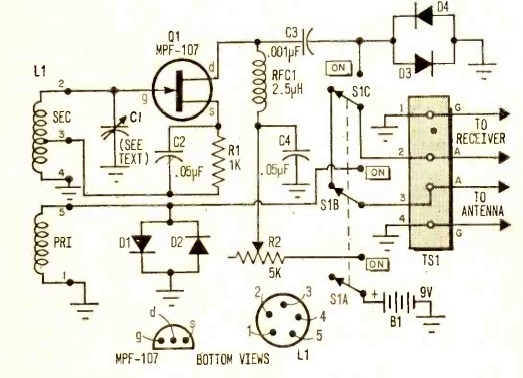
The DX Devil was a one-transistor (MPF-107 FET) regenerative preamplifier, which gave 40 dB gain from 3-30 MHz.  In addition, it eliminated images, since the tuning was sharp enough to eliminate the offending signal 910 kHz away.  And since it was regenerative, it also served as a Q-multiplier to vastly increase the set’s selectivity.  The author noted that most shortwave sets selling for less than $75 lacked a tuned RF stage, and that the addition of the DX Devil would vastly increase both sensitivity and selectivity.

Three plug-in coils allowed for band selection.  The article noted that the unit’s performance would be especially noticeable on higher frequencies.  Tuning was accomplished with a vernier dial to allow amplification of a very narrow bandwidth.  In operation, the regeneration control was set to just below the point of oscillation, ensuring maximum gain.

The author noted that the performance of the DX Devil would be inversely proportional to the quality of the receiver used: “The worse your set is, the more startling will be the results.” He reported that on a pre-WW2 receiver, 28 MHz signals were lifted from inaudibility to 100% copy. But even on a modern dual-conversion superhet, he reported much more readable signals, with the S-meter jumping 20-30 dB.

Operation of the unit would require two hands.  First, you would tune the receiver to the desired frequency.  Then, you would rock the tuning control back and forth while slowly increasing the regeneration.  I imagine that it would take a bit of practice, but eventually, you would find that the signal strength had jumped considerably.

Despite being concealed in the cover photo, the DX Devil did require a direct connection between an external antenna and the antenna terminals of the receiver.  The four diodes shown in the circuit were to provide protection in case the DX Devil was used in close proximity to a transmitter, or in case of static discharges.  At the low signal levels, they would have little effect on the circuit, but when presented with a stronger signal, they would provide a low-impedance path to ground.
1968SepEEschematic

The designer of this circuit is a familiar name to readers. The circuit was designed by the author of the article, Hartland B. Smith, W8VVD, currently licensed as W8QX.  He was first licensed in 1941, and was the author of many construction articles, such as one for a steam-powered transmitter previously featured here.  He was also the creator of the HART-65 transmitter.  A link to some of his websites can be found at the steam-powered transmitter post.  Tomorrow, we’ll bring you an even more interesting article by the same author from 1958.

Most times when I post an illustration such as this of a completed project in use, I need to take a certain amount of poetic license to name the characters.  So ordinarily, I would probably assign the name “Junior” to the young SWL, and “Fido” to his canine companion.  But in this case, such artistic license is not necessary, since the magazine gives the full name of the SWL, namely, one Gary Bulger.  And the dog’s name is Gladys.

I wasn’t able to track down Mr. Bulger, who I’m guessing lived in the New York area in 1968, since that’s where the magazine was based.  But people Google their names from time to time, and if you are the young Mr. Bulger shown in the photo, we would love to follow up with your recollections of this photo.  Please comment below or e-mail me at clem.law@usa.net.


Science Fair Project: Electricity Through Glass

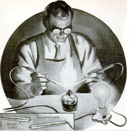
1938SepPSIf you’re looking for an interesting but slightly dangerous experiment for your science fair project, you’ve come to the right place, with this project from the August 1938 issue of Popular Science. With just a few odds and ends from the hardware store, you’ll be able to cause an electric current to flow through glass.

You’ll need some copper wire (which can be cannibalized from the electric light you’ll be using, as well as some glass tubes.  If you can’t find the glass tubing locally (or “borrow” a couple from your science teacher), then one of the least expensive options appears to be these reusable glass drinking straws from Amazon or these glass test tubes.

You’ll need a lamp cord similar to the one shown here, or you can simply use a normal desk lamp.  Cut one of the two wires leading to the lamp (or plug it into an extension cord and cut one of those two wires), and strip the insulation off the end of the two wires.  Insert each wire into a glass tube.

Of course, glass is an insulator, so the lamp won’t work when plugged in.  But when you hold the two glass tubes next to each other and heat them in a bunsen burner, electricity will begin arcing through the molten glass, and the light will come on.

It appears that what’s happening is that an oxide of the copper is mixing with the molten glass, and the current is using this as an electrical path.  When you remove the glass from the flame, the light will stay lit until the glass again solidifies.

Warning:  This experiment uses household electricity, which can kill you if you’re not careful.  Don’t work in a wet area or anyplace where you can touch a metal object.  Whatever you do, don’t let anyone touch either of the two exposed wires.  When you’re done with the experiment, cut the plug off your modified cord so that some younger kid won’t plug it in and get electrocuted.  Do this experiment only with adult supervision.


Copper Coil Winding Hint

1938SepSWcraftThe September 1938 issue of Short Wave & Television shared this hint for winding transmitter inductors from copper tubing, without kinking the copper. Before winding, place a cork in one end and fill the tube with sand. Then, plug the other end. The sand exerts an internal pressure which keeps the tubing from collapsing.

The idea had been sent in to the magazine by one Donald E.A. Rose.


Lew Brock, WCCO 1943

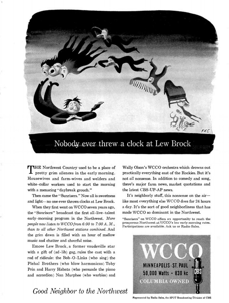
1943Aug30BCThis ad for WCCO Minneapolis appeared in Broadcasting magazine 75 years ago today, August 30, 1943.  It reminded advertisers that the station’s 6-7 AM program, time on which could be booked at the early morning rate, was hosted by Lew Brock, who had a loyal following with the station’s loyal listeners.

According to the ad, former vaudeville star Brock emceed the “Sunrisers” program, which included an orchestra and other musical regulars.


1948 One Tube Reflex Reciver

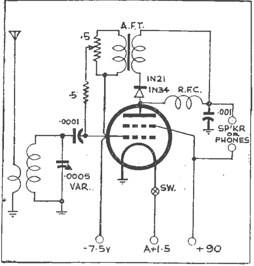
1948AugRadioScienceSeventy years ago this month, the August 1948 issue of the Australian magazine Radio Science carried this circuit for a one-tube reflex receiver capable of driving a speaker.  The circuit called for a 1C3GT tube, but noted that any one-volt tube could be used with an adjustment of the bias voltage.


1978 Solar Oven

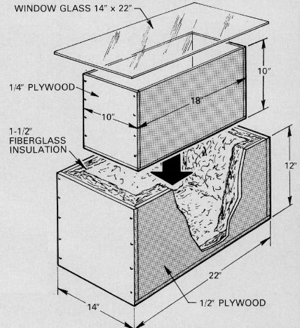
1978AugBLForty years ago this month, the August 1978 issue of Boys’ Life carried these plans for a solar oven. According to the magazine, the oven would reach 200 degrees, “hot enough to cook a meat loaf or bake breads in several hours.” The inner and outer boxes were insulated with fiberglass insulation and sealed air tight. The inside of the inner box was painted black with a “non-lead” paint. Four shiny aluminum panels could be used to direct heat into the oven.

A suggested improvement to increase efficiency was to use a double layer of glass with an air gap between the two panes.

If you would prefer to have someone else do the construction work, the solar oven shown at left is you can find  this solar oven Amazon which appears to have good reviews.


1958 Popular Electronics Two-Transistor Transmitter

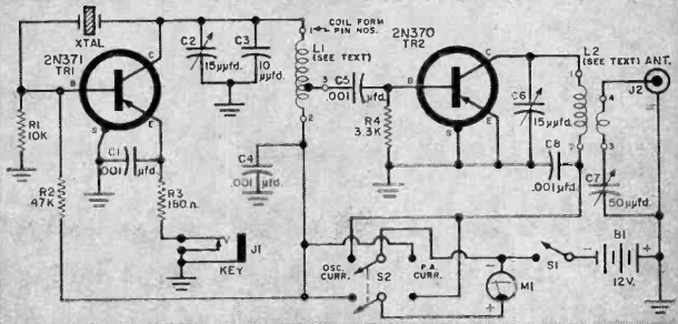
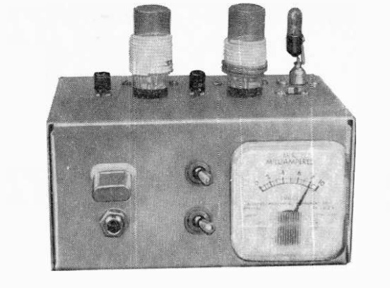
1958AugPESixty years ago this month, before QRP was cool, the August 1958 issue of Popular Electronics carried the plans for this QRP transmitter for 15, 11, and 10 meters.  The set was dubbed the Semiconductor Space Spanner. The two-transistor transmitter had an input power of 96 milliwatts. The author, Don Stoner, W6TNS reported contacts all over the continent and as far away as Hawaii. While some of those contacts were pre-arranged, many were the result of a normal CQ.

The cost of the parts was said to be $19, less crystal. A 40 meter crystal was used on 15 meters, although the circuit pulled the signal somewhat below the exact third harmonic.

The circuit used a 2N371 transistor as oscillator, feeding the 2N370 final amplifier.

If the author’s name looks familiar, readers will recall that he was the designer of an early CB rig which served as the prototype of the Heathkit CB-1 and “Benton Harbor Lunchbox” transceivers for 2, 6, and 10 meters.

1958AugPE2


Charles Atwater, 2JN

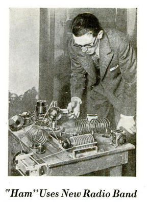
1928AugPSShown here in the August 1928 issue of Popular Science is Upper Montclair, NJ, ham Charles K. Atwater (no relation to Atwater Kent) with his 10 meter transmitter. According to the magazine, Atwater had added another triumph for the hams, namely use of the “remarkably low wave length of ten meters.” With his low powered transmitter, he established two-way contact with two stations on the Pacific coast, and had earlier made contact with Arachon, France.  The French contact was apparently with F8CT, as recounted on this page.

Atwater had been a ham for a while, since he was listed in the 1916 callbook and 1921 callbook with the call sign 2JN, with an address of 40 Oakwood Avenue, Upper Montclair, NJ.

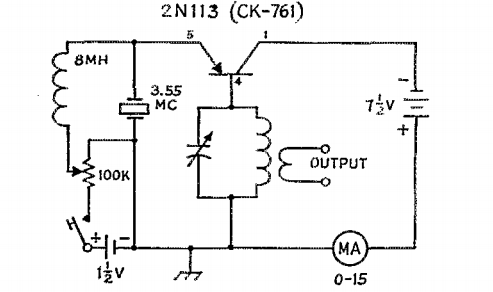
AtwaterQRPHe remained active, as shown by this one-transistor transmitter circuit he submitted (with his call now W2JN) in the December 1955 issue of QST.

According to QCWA, Atwater died in 1980.


Battery Charging, 1918

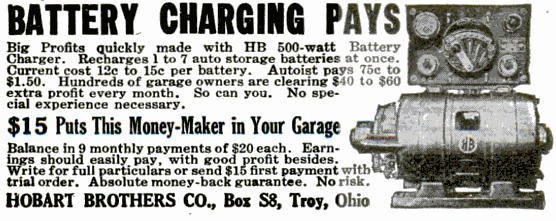
1918AugPSA hundred years ago, the entrepreneur couldn’t go wrong by getting into the lucrative battery charging business, as shown by this ad in the August 1918 issue of Popular Science.

The unit appears to be a gasoline-driven six-volt 500 watt generator, capable of charging one to seven auto batteries at a cost of 13-15 cents per battery.  The ad reports that autoists would pay $0.75 – $1.50 for the service, meaning that garage owners were clearing $40 – $60 extra profits per month.

The set was available from Hobart Brothers Co. of Troy, Ohio, for $15 down plus nine payments of $20 each.  The company is still in business, today focused on the welding industry.