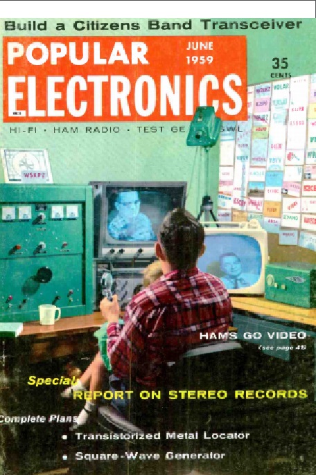
 Seventy years ago was the Goolden Age of Television, as conclusively proven by this article in the March 1949 issue of Popular Science. It details a most interesting program, namely, a live play-by-play of the construction of a shortwave receiver.
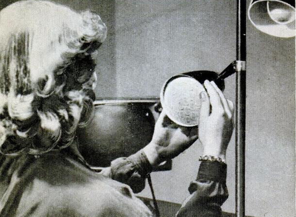
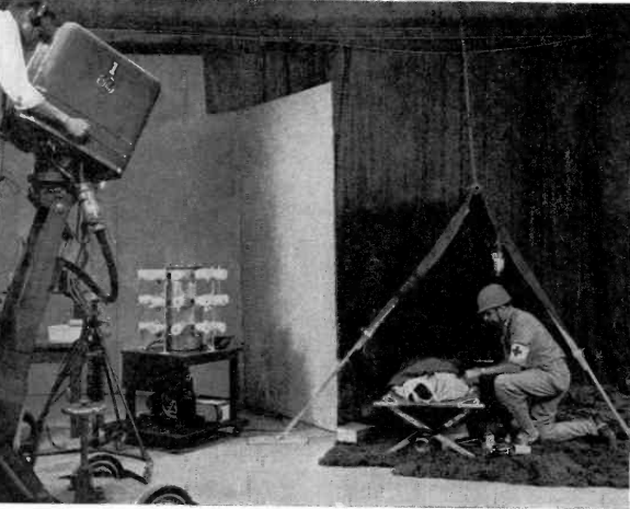
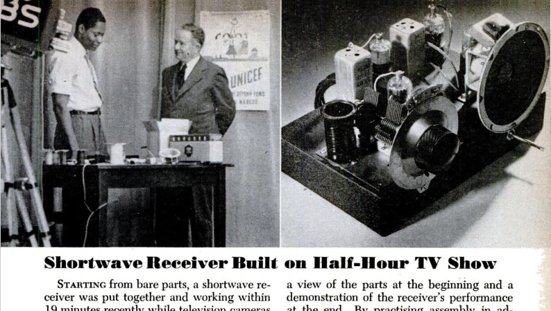
Starting from scratch, sound man Rudy Winston (shown at left in the photo) got the set working in 19 minutes while the live cameras of WCBS-TV looked on. The program was 30 minutes, but Winston had only 25 minutes, since the script called for a demonstration. But he was pulling in overseas stations with six minutes to spare.
The feat took place on the station’s “United Nations’ Casebook” program. The purpose was to “dramatize one of the world’s greatest needs–inexpensive, sturdy shortwave receivers.”
Today, inexpensive sturdy shortwave receivers, such as the ones shown below, are readily available. The models shown here can operate from power sources including solar or hand crank, meaning that they can bring shortwave reception to any point on earth. What we need more of are television shows demonstrating how they can be put together.
And, of course, if you get booked to go on TV to build a shortwave receiver, one of these kits will probably allow you to complete it in the course of a half-hour program:
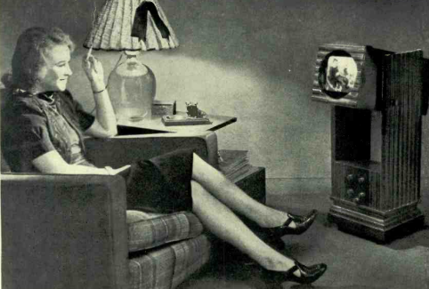
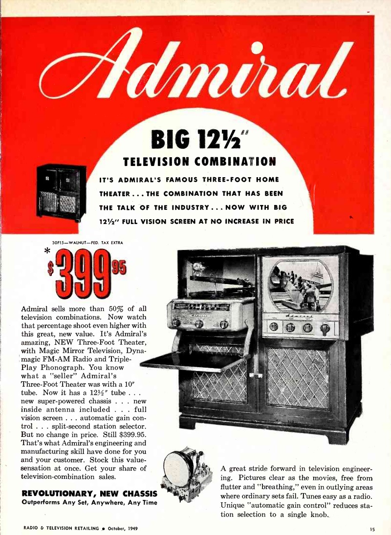 Seventy years ago this month, the October 1949 issue of Radio & Television Retailing carried this ad for a top of the line Admiral console, the model 30F15. The ad noted that Admiral had a 50% market share when it came to television combinations. This one combined an AM-FM receiver, record player, and 12-1/2 inch TV.