Category Archives: Science fair ideas

Science Fair Idea: Remote Fire Extinguisher

1940JulyPS3If Junior decides to do this science fair project from the the July 1940 issue of Popular Science, he should probably change the name. The magazine calls this gadget a carbon dioxide “gun,” and he’ll probably get in a lot of trouble if he calls it a gun. If he calls it a “remote fire extinguisher,” he’ll probably get a blue ribbon instead of a visit to the police station.

Like all young men like to do, the two shown here are playing with fire, but making a scientific point in the process. In this William Tell stunt, one young man has a candle on top of his head. The other one puts it out with the Carbon Dioxide Gun–er, I mean remote fire extinguisher. Whatever it’s called, the device is simply a can with a balloon stretched over one end. Inside, a piece of dry ice is placed. When the balloon drum is tapped, an invisible cloud of CO2 is expelled, which causes the flame to be deprived of oxygen.


Electric Hot Dog Cooker

1960JulyEE4I suspect many of our readers have independently invented the idea shown here for an easy way to cook a hot dog. You simply run 120 volts through the hot dog, and the hot dog serves as a resistor and cooks itself. This incarnation of the idea was designed by prolific electronics writer Len Buckwalter and appeared in the July 1960 issue of Electronics Illustrated.

This design is a bit safer than what I remember doing. While cooking, the hot dogs are safely concealed inside a bakelite box. They don’t start cooking until the lid is inserted, since the cord is part of the lid, and there’s a TV-style safety interlock.

The young scientist wishing to come up with an interesting science fair project won’t go wrong with this idea. It give a great demonstration of Ohm’s law and the power law. And sharing the hot dogs with the judges certainly won’t hurt in earning that coveted blue ribbon.

Of course, you don’t want to be disqualified by electrocuting one of the judges, so it’s best to come up with some form of interlock.

The venerable Presto Hot Dogger used the same principle to cook hot dogs. It unfortunately seems to be out of production, but they show up on eBay.  But making your own is easy, and a lot more fun.


Paper Clip Motor

1940JulyPS2If you’re looking for a science fair project that can be put together with parts you’ll find around the house, you can’t go wrong with this motor from the July 1940 issue of Popular Science.

The main components used are paper clips. You’ll also need some insulated copper wire and a few other odds and ends. The old-fashioned dry cell batteries look cool, but it will work just as well with a couple of alkaline D cells.


Electrostatic Generator

1970JunSciElecFifty years ago this month, the June-July 1970 issue of Science and Electronics showed how to put together this electrostatic generator, as well as the accompanying Leyden jar and electroscope.

It consisted of a plastic jar which was turned by the crank to rub against a piece of wool. A pickup wire collected the charges and conducted them to the metal ball. This could be used to charge the Leyden jar. For bearings, the device used roller skate wheels.

1970JunSciElec2Emergency preparedness buffs will notice that the electroscope, at left, looks very similar to the venerable Kearney Fallout Meter (KFM) used for detecting nuclear radiation. Indeed, they do rely on the same principle. In the presence of ionizing radiation, the charge will slowly dissipate, allowing the leaves to get closer together. This electroscope is not calibrated. Therefore, it would not be able to provide an accurate radiation dose reading. However, this generator would be useful to charge the KFM.

For young scientists without any ionizing radiation at their disposal, the magazine describes a number of interesting experiments, any one of which would be sure to bring home the blue ribbon at the next science fair.  To guarantee the top prize, one interesting experiment would be to purchase a small uranium sample.  Charge up the electroscope and see how long it takes to discharge.  Then, repeat the experiment with the uranium inside the electroscope and see how much faster it discharges.


1940 Fire Science Experiments

1940AprilPS2Sadly, the school Science Fair is probably cancelled this year, but that doesn’t mean Junior can’t enjoy some exciting science experiments at home, such as the ones described 80 years ago this month in the April 1940 issue of Popular Science.

Actually, it might be a good thing that the official Science Fair is cancelled. It’s unlikely that the science teacher would sign off on these experiments, since they amount to playing with fire, and it would be hard to tie them in to the scientific method of inquiry. But they do have a redeeming scientific value of getting Junior excited about science, and they look like fun, as long as they are done in the backyard far away from any combustible objects.

The best experiment is shown above, where a line is traced out and then used as a racetrack for a race of fire.  A “pinch or so” of potassium nitrate (also known as saltpeter) is dissolved in a teaspoon of water.  This is used as ink, and the race course traced on a piece of paper.  When the paper is dried, the starting line is ignited with a “lighted match or cigarette tip.”  (Due to a pandemic of respiratory illness in progress, we advise against using a cigarette.)  Trails of fire then appear, racing to the finish line.  You can order the potassium nitrate at Amazon.


Science Fair Idea: Eli the Ice Man

1945MarRadioCraftAIf you ask any serious student of electricity to name their favorite ice man, they’ll undoubtedly tell you that it is Eli. Eli the Ice man (a friend of Roy G. Biv) is a mnemonic to help you remember that in an inductive circuit (L), the voltage (E) leads the current (I). And in a capacitive circuit (C), the current (I) leads the voltage (E).

You can prove this concept with this simple experiment shown 75 years ago this month in the March 1945 issue of Radio Craft. In addition to the capacitor and inductor and a few miscellaneous parts, you’ll need a voltmeter and ammeter. During the war, those analog meter movements would have been hard to come by, but these days, you can get buy with two cheap multimeters. Stores sometimes give digital meters away for free, but this experiment will look a lot cooler with an analog meter.

You wire up the circuits and then observe the meter when the current is turned on. In the capacitive circuit, the ammeter will move before the voltmeter. In the inductive circuit, it will be the other way around.


1935 Light Beam Communicator

1935MarPM85 years ago this month, the March 1935 issue Popular Mechanics showed how to make this light communicator, said to have a range of about a half mile.

The receiver used a caesium photo cell, which the magazine said could be had for about $3. This was fed into a two-tube amplifier which could drive a speaker or headphone.

For audio amplification at the transmitter end, the system used the household radio receiver, and the magazine explained how to hook up the microphone. The the light beam generator used a system I’ve never seen before. Instead of electrically modulating the light bulb, a mechanical approach was used. The speaker was disconnected and the output was instead connected to a magnetic headphone that had been modified. The outer cap of the headphone was unscrewed and cut so that most of the metal diaphragm was visible. Then, the “diaphragm is slipped off and taken to any plating firm to be finished in the same manner as an audio headlight reflector.” The headphone was reassembled, and the result was a mirror that would vibrate in time with the sound. An auto headlamp was used to illuminate the mirror, and this was focused through a lens with a focal length of about 12 inches.

The result would have been a narrow beam of light that was modulated. At the receiving end, another lens was used to focus the beam on the photo cell.

For a unique science fair project, the advanced student could adapt this project using modern materials.  When I was a kid, I built a similar system using a flashlight as the transmitter.  The bulb was wired in series with the secondary of an audio transformer.  The primary was fed by the output of an amplifier.

For the receiver, I used a solar cell fed directly to the input of an audio amplifier.

1935MarPM2


Science Fair Idea: Homemade Seismograph

SeismometerFor the aspiring scientist who is interested in earthquakes, today we show you how to build your own seismometer. If you started by searching for “science fair seismograph,” you were possibly disappointed at the initial search results. You undoubtedly found sites showing how to make a toy seismosgraph out of materials such as cardboard boxes. I’m sure these were fine projects for less advanced students, but they weren’t real seismographs. Instead, they were models that showed how a seismograph worked. You build the toy instrument, and then jump up and down in close proximity, simulating an earthquake.

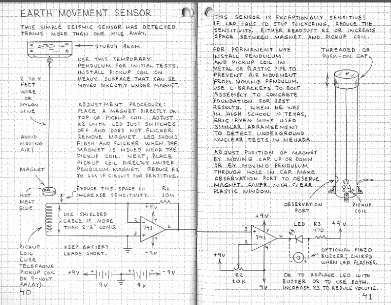
We are glad that you kept searching, because we will show you how to build a real seismometer or seismograph, one capable of detecting distant earthquakes.  If there are no earthquakes before the science fair, you can test the unit with nearby trucks and trains as they pass by.  The unit shown here, for example, picked up trains a mile away.  In addition, a very similar unit was used, in Texas, to detect underground nuclear tests in Nevada.  So it’s not a toy–it’s a real seismometer.

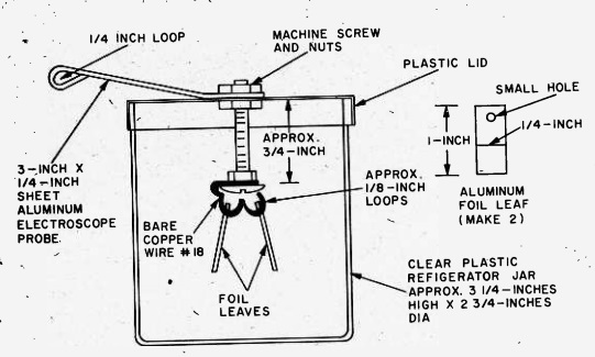
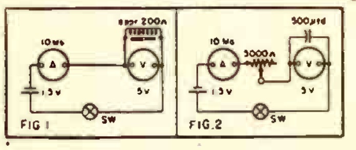
The overall concept is clear from the diagrams shown above.  A magnet is suspended from a wire or line attached to a sturdy beam of your building.  In the final version, this pendulum is placed inside a pipe, to prevent air currents from disturbing it.  The magnet is placed above a coil, and the slightest motion of the pendulum, caused perhaps by an underground nuclear test hundreds of miles away, induces a tiny electrical current in the coil.  This is amplified by two op amps, and registers with an LED and/or a piezo buzzer.

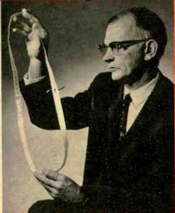
As shown in the diagram, the instrument is a seismometer, since it detects seismic activity.  To turn it into a seismograph, you will need to add some method of recording the readings continuously.  However, that is a very easy matter, thanks to a data acquisition module, similar to the one shown at left.  This is a very inexpensive device that hooks to the USB connection of your computer.  It has several inputs that you can hook to a circuit, and it continually feeds the measured voltage to the computer.  You can then use the computer to record the data numerically or in a graph.

All of the other parts are readily obtainable.  From Amazon, you can order the telephone pickup coil, the 741 op amp chips, and all of the other electronic components.  (For ideas on how to buy parts, see my crystal set parts page.)  All of the mechanical components should be available in any hardware store.

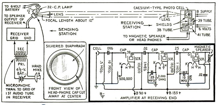
The diagram above is from a book by Forest Mims III, Engineer’s Mini-Notebook:  Science Projects, one of a series sold at Radio Shack.  This particular volume was published in 1990.  It’s available free online.  The same author has another version of the seismograph at this site.  You can also visit his website, forestmims.org.

Incidentally, as you can see above, the book contains the phrase, “when he was in high school in Texas, Eric Ryan Mims used a similar arrangement to detect underground nuclear tests in Nevada.” There is a multimedia CD by this long title by Canadian musician Matt Rogalsky. Inspired by that phrase, Rogalsky processed the output into ambient sound. While it is out of print, used copies are available on Amazon.
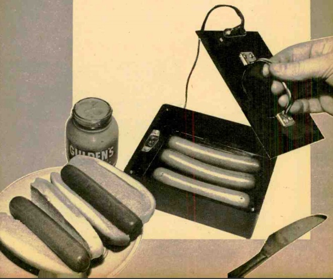


Science Fair Idea: What Melts Faster–Clean or Dirty Snow?

1939DecPSIf Junior’s science fair project is due tomorrow, there’s plenty of time for him to take home the blue ribbon, as long as there is snow on the ground. The science teacher demands that the experiment answer a question, so Junior’s question will be: “Which melts faster–clean snow or dirty snow.”

It turns out that the dirty snow will melt faster. This is because the dark particles soak up heat, while the pure white snow reflects it. To prove it, Junior can set up the experiment shown above.

You will need a table lamp with an old-fashioned incandescent bulb. For this experiment, you do not want an “energy efficient” bulb. They are energy efficient because they generate less waste heat, but for this experiment, you want to generate heat. So the most inefficient bulb wins.

To accurately measure the rate of melting, the snow is placed on a piece of screen on top of a glass. There are two ways Junior can do the experiment. He can wait until all of the snow melts, and see which one melts first. Or, he can stop the experiment after a certain time and measure the water to see which one has more.

The teacher will be most impressed with Junior’s ingenuity. He or she will think that many weeks of planning went into it. Actually, 80 years of planning went into it, since the experiment appeared in the December 1939 issue of Popular Science.


The Möbius Resistor

1969NovEI

Mobius resistor. Wikiepdia image.

Shown here in the November 1969 issue of Electronics Illustrated is Richard L. Davis of Sandia Laboratories, the inventor of the Möbius resistor, US Patent 3267406A.

Many youngsters will be familiar with the Möbius strip. It’s a three-dimensional object with one side and one edge. It is formed by taking a strip of, for example, paper, making a twist, and then taping the ends together. To prove that it has one side, the young scientist can draw a line down the middle. Eventually, the line will connect up, but only after covering “both” sides of the strip, in effect proving that there is only one side. The strip can also be cut along that line, which will form another strip, this one non-Möbius.

Davis used the Möbius strip to form a resistor. His strip of paper was coated with foil. When it was attached together. The outside of the strip formed a continuous conductor, and connections were made directly opposite. The result was that current was flowing on the outside of the strip, but in opposite directions. Therefore, the magnetic fields cancelled out, making the resulting device non-inductive. This proved useful at UHF, since the stray reactance of a resistor would otherwise be very significant at those high frequencies.

Students looking for an interesting science fair project could make either a Möbius strip or a Möbius resistor.  A student will almost certainly get a participation ribbon by making the strip and then unsuccessfully attempting to cut it in half.  But more advanced students, armed with an inexpensive RCL meter, can get the blue ribbon by showing that the inductance disappears by adding the twist to the strip.