Category Archives: Science fair ideas

Science Fair Idea: Home Energy Efficiency

Here’s an idea for students looking for an interesting science fair project, or for those who are simply nosy and want to see if their neighbors are wasting energy.

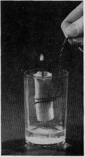
For those of us who live in cold climates, it’s easy to keep track of how much energy your neighbors are using for heating. For any house with a conventional gas, oil, or coal furnace, there’s an easy indicator telling you exactly when their furnace is running. There’s a vent on the roof of the house, and when the furnace is running, you can see steam rising from it. When the furnace is turned off, the steam quickly disappears. (The water vapor might not be visible when the temperature is high enough, but on cold days, the effect is readily apparent.)

Furnace is on.

Furnace is on.

This means that just by looking at a house, you can tell if the furnace is on. By keeping an eye on it for a few hours, you can determine what percentage of the time the furnace is running. Families who are conserving energy by turning down the thermostat a few degrees, or those who have well insulated houses, will have the furnace on fewer minutes per hour, saving money and energy.

For a science fair project, the student is usually expected to design an experiment that answers a question. The easiest question would be, “how does temperature affect fuel consumption.” By monitoring on different days with different temperatures, you can make a chart showing that when the temperature goes down, the amount of time the furnace runs, and hence the amount of fuel burned, goes up. Or you could compare different houses, and answer the question of whether a _____ house uses more energy than a ____ house. You can fill in the blanks as you please.

Furnace is off.

Furnace is off.

Since numerous chimneys are probably visible from your house, you can conduct the entire experiment from the comfort of your own home.


Transformer Science Project


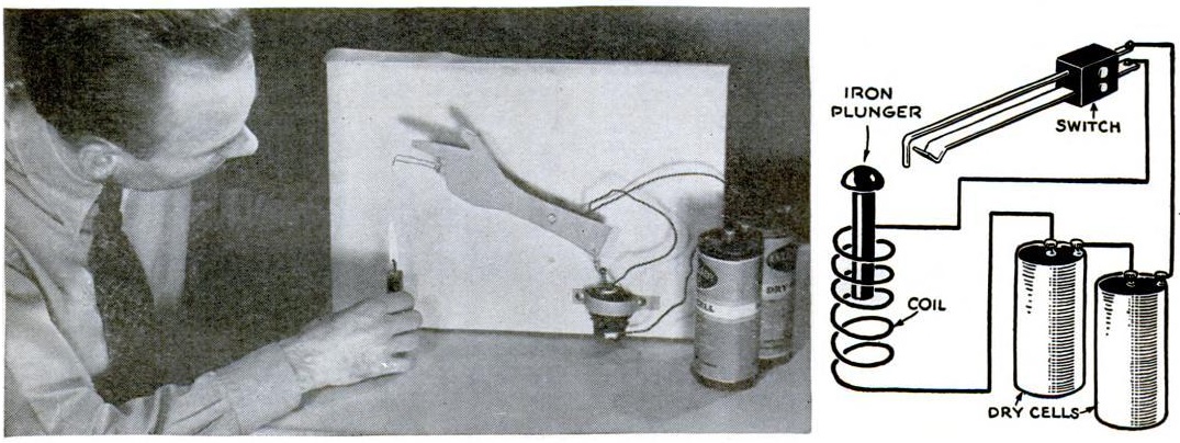
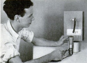
1946FebBL75 years ago, this young man discovered the secret for meeting girls. That, of course, was explaining to them how transformers worked. This young woman is obviously mesmerized by his explanation.

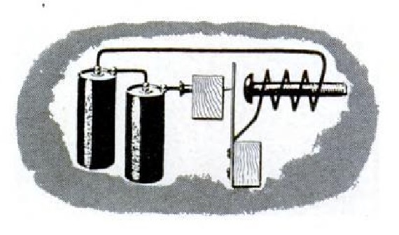
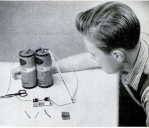
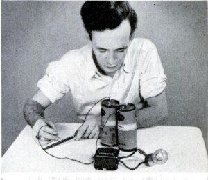
He gained this skill by conducting the experiment shown below. He constructed his own transformer with two coils of wire wound around an iron core. To provide the alternating current, he runs one wire along the file.

1946FebBL2

These items appeared as part of an for Westinghouse in the February, 1946, issue of Boys’ Life.  It reminded readers to tune in to programs sponsored by the company, John Charles Thomas and Ted Malone.

The science project is easily duplicated today.  While the old-style dry cell battery is no longer available, an alkaline D cell, with suitable holder, would work just fine.  The other items needed are wire, the bulb (with socket to make the connections easier), an iron bar, and file.


Science Fair Ideas: Measuring the Moon’s Diameter

1941FebPSIf Junior is looking for a science project that can be completed in one evening, the teacher will be suitably impressed when Junior announces that he will measure the diameter of the Moon. All that’s required is a window through which the moon is visible and a couple of pieces of tape. Masking tape would probably work the best, but you could also use a couple of Post-It notes. You’ll also need a card through which you cut a hole.

Place the strips of tape on the window 1-1/4 inches apart. Then, you move the card away from the window, and keep looking through it until the moon appears to fill the space between the two pieces of tape. Measure the distance between the card and the window. At this point, the proportion of the two distances is the same as the proportion between the moon’s diameter and the distance between the moon and the earth.

Let’s say, for example, that Junior measures the distance between the card and the window as 137-1/2 inches. (Ahem, and if he does the experiment correctly, that’s the number he should get, assuming that the moon hasn’t changed size.)

According to NASA, who has been there, the moon is 238,855 miles from the earth. So we have a ratio:

1.25 / 137.5  =  X / 238,855

If Junior’s algebra is a little bit rusty, he can use this online calculator to get the answer of 2171.4 miles. According to space.com, the actual diameter is 2159.2 miles, so we would say that Junior’s method is pretty close.

1941FebPS2The experiment appeared 80 years ago this month in the February 1941 issue of Popular Science, which also carried some other astronomy experiments and demonstrations. For example, shown here is a demonstration of a solar eclipse, using a lamp for the sun and a tennis ball for the moon. One of these would be an excellent project in preparation for the June 10, 2021 annular eclipse or the April 8, 2024, total solar eclipse, both of which will be visible in North America. The magazine even shows how to demonstrate the orbit of a comet using an electromagnet to simulate the sun’s gravitational pull on a steel ball simulating the comet.


Light Bulb Illusion

1946FebPSWe would be hard pressed to come up with any scientific principle that is established by this demonstration, but it’s a clever illusion, and if Junior’s teacher is the charitable sort, we’re sure that this project would be a most welcome diversion at the next science fair.

The light bulb seemingly glows without being hooked up to anything. As you can see from the diagram, this is accomplished by taking the base from a burnt out bulb and carefully attaching it to another bulb.

The idea appeared 75 years ago this month in the February, 1946, issue of Popular Science.


Science Fair Idea: Barkhausen Effect

1941JanRadioTV2The young scientist wishing to create a simple but spectacular science fair project is almost assured of taking home the blue ribbon by duplicating the 1919 experiment of German scientist Heinrich Barkhausen establishing the domain theory of magnetism. When a piece of ferrous material is magnetized, it does not magnetize evenly. Instead, tiny pieces of material are magnetized together in discrete pieces. This is known as the Barkhausen effect.

Stamp Heinrich Barkhausen.jpg

Barkhausen on 1981 East German stamp. Wikipedia image.

To prove this, a coil is wrapped around a piece of iron, and the coil is connected to the input of an audio amplifier. As a magnet is brought toward the coil, static is heard in the speaker. But if the iron core is removed and the experiment repeated, the static is absent. A simulation of the effect can be found at this link.

Replica of Barkhausen’s experiment. Wikipedia photo.

Full instructions can be found in the January 1941 issue of Radio & Television magazine. You will need 38 gauge or smaller enamel wire to wind the coil, as well as an audio amplifier and speaker.


Since Fair Project: Ferroresonance

1961JanPEIf Junior is looking for a science fair project, the teacher probably wants the students to create an experiment to answer some question. Often, the student is required to submit the question for approval. If the teacher deems the question to be appropriate, then the students are allowed to proceed with the experiment.

Occasionally, teachers have been known to be nitpicky with this process, rejecting questions based upon their personal perception of scientific merit. Therefore, there might be some advantage to proposing a question that the teacher doesn’t understand. Then, they can’t reject the question without revealing their own scientific ignorance.

We can guarantee that Junior’s teacher has never heard of ferroresonance. Therefore, if Junior proposes a project involving ferroresonance, then the teacher is bound to accept. Junior’s question could be something along the lines of: “Can non-linear inductance be used to make a ferroresonant relaxation oscillator?” It turns out that the answer is yes, according to the January 1961 issue of Popular Electronics, and it can be proven by the experiment shown here.

Ferroresonance was first described in 1907 by French electrical engineer Joseph Bethenod, and named by French engineer Paul Boucherot.

A circuit is resonant when the capacitive reactance and inductive reactance are equal. And normally, the reactance is dependent upon the frequency alone. But other factors, such as magnetic flux of the inductor, can cause non-linear effects at the time when the circuit is initially switched on.

The heart of this experiment is an old choke of more than 1 Henry, capable of handling at least 50 mA. I’m guessing that one could use an old power transformer. Remove the frame to reveal the “E” shaped core inside. From another old transformer, obtain a section of laminations, which will be laid on the top.

According to the magazine, “the point of adjustment is quite critical and requires a bit of patience.” The loose section starts completely on top of the “E”. With the switch on, the bulb should not light. That section is slowly moved, about 1/32 of an inch at a time, with the switch turned off after each move. At the critical point, the bulb will flash on and off at intervals of about 1 second.

Junior will thus have demonstrated that by varying the magnetic flux, he has introduced a non-linearity which causes the circuit to flash.

It should be noted that this experiment involves 120 volt electrical current, so proper precautions should be taken.


1945 One Tube Broadcast Set

1945NovRadioCraftSeventy-five years ago this month, the November 1945 issue of Radio Craft carried this circuit for a simple one-tube receiver for the broadcast band. The set used either a type 30 or 1G4 tube, with as little as 3 volts B+ on the plate. The circuit had been sent in to the magazine by Bill Buehrle, Jr., of Ferguson, MO, who reported that he was able to pull in a half dozen stations clearly from 25 miles away.

Even though the circuit was published after V-J Day, it’s likely that it was perfected while the War was still in progress with its attendant parts shortages. The author points out that parts weren’t critical. In addition to the tube and headphones, the circuit required only six manufactured parts, two resistors, two fixed capacitors, and two variable capacitors. The coils and the RF choke could be wound at home.

The circuit could be easily duplicated today. The tube is still readily available on eBay. The type 30 and the 1G4 are electrically identical, but my preference would by the 30, since its glass has the classic styling of the 1930’s era bottle, as opposed to the more “modern” octal style 1G4.   It’s such a simple set that it would form the basis for an excellent science fair project. And with only 3 volts involved, it would even be a safe project. The original article contains some suggestions on how the circuit could be modified, so comparing some of these modifications would make the project very worthwhile.  The young scientist needing to track down the parts will find some helpful leads on my crystal set parts page.


1960 Handwriting Recognition

1960NovEE3
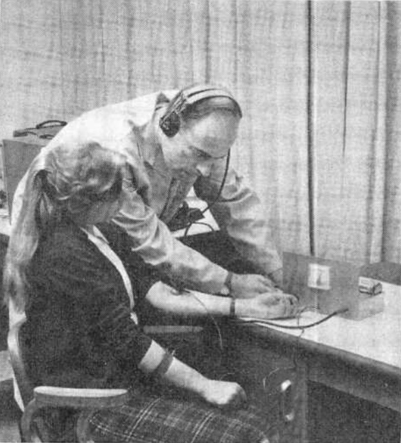
Shown here in the November 1960 issue of Electronics Illustrated is 17-year-old Belmont Frisbee, then a student at Burroughs High School in China Lake, California. He was one of the winners of the 1960 National Science Fair and is demonstrating his winning entry here. The device he constructed is dubbed “Adicof,” and allowed the entry of numbers into a computer by writing them by hand.

The digit is written with a metal stylus onto a panel with inlaid copper strips, as shown in the diagram below. For example, when making a “2”, the stylus will pass over strips 1, 2, 3, 4, 5, and 7.

The nearly forgotten art of relay logic is used to determine which number was being written. A partial diagram is shown below. Each strip is attached to the coil of a relay. The first relay is single pole, double throw (SPDT). The next one is DPDT. The one after that is 4PDT. Unfortunately, there probably weren’t any 128PDT relays on the shelf for the seventh relay, so multiple relays were used for the higher stages.

I believe the circuit shown here is simplified in one respect: For this to work, it would be necessary to use some type of latching relay, since the stylus would no longer be in contact with the pad when the next pad is contacted.

The simplified diagram shown here uses light to indicate the digit drawn, but for his exhibit, Mr. Frisbee hooked the output to a computer.

Today, it’s a trivial matter for a computer to recognize hand input, but the concept is nothing new. Sixty years ago, a high school student accomplished the task with electromechanical relays.

Mr. Frisbee continued as an engineer after high school. He was issued at least two patents (4,477,812 and 8,009,084), both of which involve radar, and both of which list the U.S. Navy as the assignee.

The magazine highlighted some other winners of the 1960 National Science Fair. Remarkably, it includes an electron microscope constructed by Marvin Hutt, a New York high school student, despite having experts tell him that making one at home was impossible. For students looking for inspiration for a science fair project, perhaps there are a few who could build an electron microscope from scratch. But in an age when computing power is taken for granted, there’s something to be said for being able to use mechanical relays for programmable logic. The science teacher might not even realize that it’s possible, and proving the impossible is always a good way to take home the blue ribbon.

1960NovEE4


1970 Soviet Fax Machine

SovietFaxThe magazine doesn’t show all of the construction details, but if you want to be accused of Russian meddling in the science fair, here’s the project for you. For the young Soviet comrade wishing to take home the blue ribbon in the oblast science fair, the November 1970 issue of Юный техник (Young Technician) magazine gave enough information to build a fax machine. Apparently, it was called a “phototelegraph-integrator”, since that is the title shown here.

Both of the drums are spinning at exactly the same speed.  A scanner is moving across one of them, and a printing element, such as a pen, is moving across the other one, at exactly the same speed.  One of the machines scans a picture of the word Mir (peace), and this is transmitted to the printer, which makes an exact facsimile.

The bright American student can also build a device that can transmit pictures through a wire. The key is to have two drums that are spinning at exactly the same speed. The easy way to accomplish this, for demonstration purposes, is to simply have both of them revolving together on the same shaft. Both of them need to have something that moves along the drum at exactly the same speed. The easy way to do this, for demonstration purposes, is to have the sending and receiving elements connected together with a shaft.

One of those elements needs to have a method to detect the picture. In a fax machine, that’s done with light. But an easy way to do it, for demonstration purposes, is to create the image using aluminum foil. Then, the sensor can be nothing more than a piece of wire that comes into contact with the foil.

This wire is hooked to a circuit which operates a solenoid. The solenoid raises and lowers a pen which comes into contact with the other drum. Whenever the wire on the sending drum comes into contact with the foil, the circuit is closed, and the pen starts drawing on the other drum.

Turn the drum while slowly moving the two sensors. The result will be a drawing exactly the same shape as the piece of foil.

The crude drawing below shows the general idea. An advanced student should be able to work out the invariable bugs and build their own fax machine. When you take home the blue ribbon, the other students will probably accuse you of winning due to Russian meddling. When they do, point out that there was nothing in the rules prohibiting it.

FaxMachine


Science Fair Idea: Jacob’s Ladder

1960NovEE5This young woman undoubtedly took home the blue ribbon in the 1960 science fair. And she certainly earned herself considerable street cred as a mad scientist by putting together this Jacob’s ladder, by carefully following the plans in the November 1960 issue of Electronics Illustrated.

As revealed by the schematic diagram below, the circuit is simplicity itself. It simply takes normal household current and runs it into a transformer which steps it up to 12,000 volts, which is fed into two electrodes. One way or another, there is going to be an arc between the two conductors. It will follow the path of least resistance, and thus starts out at the bottom, where the two metal rods are closest together.

The arc heats the air right above it, which ionizes the air. The ionized air thus becomes the new path of least resistance, and the arc moves upward. The process repeats until it reaches the top, at which point a new arc forms at the bottom.

The critical component, of course, is the high voltage transformer. In 1960, it was available in the form of a neon light transformer, for $12 plus shipping. Of course, neon signs still exist, and you can buy the transformers on Amazon.  This modern replacement is rated at “only” 10,000 volts, but it seems like that should be sufficient.

The 1960 article includes a number of important safety features. First of all, the electrodes are safely behind a sheet of 1/32″ clear acetate. This also appears to be available on Amazon.

And the choice of switch ensures that the device isn’t turned on accidentally. The power switch is a momentary switch, meaning that when you let go of the switch, it turns off. It’s a SPDT switch, meaning that when it’s off, another contact is energized. This is wired to a green pilot light that indicates that the device is plugged in. The switch has a safety cover, meaning that one needs to consciously lift the cover to flip the switch.

The article begins by saying that “if the directions given in this article are followed to the letter, there is no danger of shock. Don’t take short-cuts or omit the built-in safety features of this model; it is poor economy to leave out relatively inexpensive components that might prevent a nasty shock.”

These days, when one reads safety warnings, there’s a tendency to ignore them. But in 1960, when a warning like this was included, it’s because the activity in question was, indeed, dangerous, and you really needed to be careful. So I believe this project is suitable for mature students, working under the supervision of a competent adult. But this contraption is potentially lethal, and great care must be taken in its construction and use.  In 2016, a Michigan teen was killed trying to build one, and we don’t want any of our readers to suffer the same fate.  So please be careful.

1960NovEE6