Category Archives: Radio

ARRL 100th Anniversary

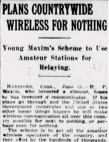
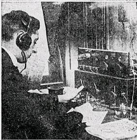
ARRLnewsitemA hundred years ago, the New York Sun for June 14, 1914 reported on the beginnings of the ARRL.

The article announces that “H.P. Maxim, who invented a silencer, hopes he has invented a communicator.” It outlines Maxim’s plan, which is generally what the ARRL accomplished soon thereafter. “The scheme is to get all the amateur wireless operators of the country, and they exist by the hundreds of thousands, interested in transmitting messages from coast to coast.” Maxim is quoted that the proposal is to “select those stations which are able to transmit from fifty to 100 miles and which are kept in perfect running order. And then all stations in the league which we are forming, to be known as the American Radio Relay League, will at a predetermined hour ‘listen in.’ That hour will probably be 7:30 each evening.”

Maxim points out that the intention is “to make this thing strictly amateur. The messages are to be relayed by courtesy. There will be no fees for receiving, delivering or relaying the messages. No money transaction of any kind is to be considered in connection with the league.”

He also notes that the Government is likely to be cooperative, since the relay proposal ensures that it “will make it unnecessary for an amateur to have a high powered set,” thus reducing interference.

The War slowed things down a bit, but the first “Transcon” test was successfully carried out in January, 1921, with a successful transcontinental message and reply in “two hours flat.”


Soldatensender Calais and D-Day

D-Day Landing (U.S. Army photo)

D-Day Landing (U.S. Army photo)

The complete broadcast day for D-Day, June 6, 1944, was recorded by both CBS and NBC. One detail that I always found interesting was the following wire report, which was also carried in print by the AP in the D-Day afternoon papers:

Music for Invasion Forces

About the same time the German controlled Calais radio station came on the air with the following announcement in English:

“This is D day. We shall now bring music for the invasion forces.”

The whole Nazi controlled French radio network went off the air at 7:25 a.m. in the middle of a physical training broadcast.

Milwaukee Journal, June 6, 1944.

I’ve never seen any explanation of this curious statement, although the impression was that the French personnel of the station had taken advantage of the chaos and taken over the station.

The truth, however, appears to be even more interesting. It seems likely that the “German controlled Calais radio station” was actually Soldatensender Calais, a German-language station operated not by the Nazis, but by the Political Warfare Executive of the British Foreign Office. Soldatensender Calais (Soldier’s Station Calais) was broadcasting not from Calais, but from the village of Milton Bryan, Bedfordshire, England, with a massive 500 kilowatt mediumwave transmitter. It broadcast on 612 kHz, 714 kHz, and 833 kHz, frequencies shared by Radio Deutschland.

Joseph Goebbels himself lamented in his diary in 1943:

In the evening the so-called “Calais Soldiers Broadcast” which evidently originates in England and uses the same wavelength as Radio Station Deutschland when the latter is cut out during air raids, gave us something to worry about. The station does a very clever job of propaganda and from what is put on the air one can gather that the English know exactly what they have destroyed and what not.

The transmitter had originally been ordered by WJZ in Newark, New Jersey (now WABC, with its city of license New York), in hopes that the FCC would authorize the high power to match the superpower signal of WLW in Cincinnati which had in use on and off from 1934 to 1939. But when the FCC insisted on maintaining the 50 kW limit for standard broadcast stations, the station was eager to sell the transmitter to the British government for £165,000. At the time, the station was the world’s most powerful mediumwave station. It had the code name of Aspidistra, and remained in use by the BBC until 1982.

It was able to successfully spoof Nazi broadcasts to the point that it was regarded as a reputable source of information. When real German stations went off the air during air raids, the powerful British station would rebroadcast the signals of other German network stations still on the air, thus giving the impression that it was part of the German network. The superpower transmitter could blanket the continent, thus allowing it to join the Nazi broadcast network seemlessly. But into those programs, it could subtly insert misinformation. For example, it could be used to issue false evacuation orders to send civilians to clog the roads during German military movements. Captured German POW’s, even those who were aware of the station’s source, commended the British on the station’s plausible deniability. If a German officer walked in while the men were tuned to the station, they could plausibly claim that they thought it to be an ordinary German station.

The station’s creator, Sefton Delmer, described its programming as “cover, cover, dirt, cover, dirt.” Most of its programming mimicked the official German stations. But when needed, disinformation could be inserted. The Germans eventually figured out what was going on, and they preceded official instructions with the following announcement:

The enemy is broadcasting counterfeit instructions on our frequencies. Do not be misled by them. Here is an official announcement of the Reich authority.

Of course, the English station then began its messages with the same announcement!

The only reference I could find to Soldatensender Calais with respect to the invasion was that when Calais later fell to the Canadians, the station was renamed Soldatensender West. I haven’t been able to find any explanation as to why the station made its English broadcasts on D-Day. But it seems to me that the intention was probably to demonstrate that Calais had already fallen in the early morning hours of June 6, and that the French staff of the fictitious station had taken matters into their own hands to start broadcasting music for the benefit of the invading Allied armies.

And since the American press apparently fell for it and reported the activities of the “German controlled Calais radio,” this tactic seems to have worked.

References

Read More at Amazon:

Deutsch:


The “Foxhole Radio” Turns 70

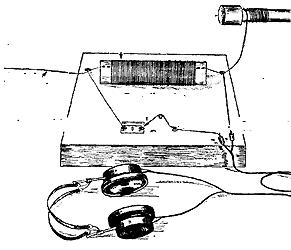
FoxholePictorialI suspect that most who are familiar with the “foxhole radio” learned about it from the 1950’s era book All About Radio and Television by Jack Gould. This book, a staple of many elementary school libraries, includes the crystal set shown here, which was constructed using a razor blade and pencil lead as the detector. Gould recounts how such a radio was used by soldiers in the fox holes of World War 2, and I suspect that it was the appearance in Gould’s book that popularized the name.  And it turns out that Gould probably originated the name.

The name “foxhole radio”, and perhaps the concept, seems to have originated from the construction of simple crystal sets by soldiers at Anzio in 1944. From March through early May, 1944, fighting was light, “living was leisurely” for the thousands of soldiers on the beachhead, and the beachhead was a “honeycomb of wet and muddy trenches, foxholes, and dugouts.”

One of the first references to the fox hole radio I’ve been able to find appeared in QST for July, 1944. It doesn’t use the term “foxhole radio,” but this “Stray” reads as follows:

According to Toivo Kujanpaa, a licensed ham op stationed on the Anzio Beachhead, several of the radio men there rigged up a field version of a “crystal” set using a razor blade for a detector. Their efforts were rewarded by the reception of a “jive” program (along with some German propaganda) aimed at the American forces from an Axis station in Rome.

About that same time was when, as far as I can tell, a variation of the name “foxhole radio” first appeared in print.  Time Magazine for July 17, 1944 made the report,.   Time reported that one Lt. M.L. Rupert was one of “hundreds of U.S. infantrymen” who made the foxhole receiver to kill time and boredom at Anzio.  Lt. Rupert wrote to Marlin Firearms Company (the manufacturer of the razor blades) with a description of the set.As QST later lamented, Time “as usual” hadn’t given credit to hams for coming up with the idea.

A similar account, also crediting Lt. Rupert’s letter to the manufacturer, appeared in the New York Times on June 25, 1944. According to the New York Times, the idea of using the pencil lead originated with O.B. Hanson, NBC’s vice president of engineering, who refined on the concept sent to the razor blade manufacturer. Interestingly, the byline of the New York Times account is none other than Jack Gould, the author of All About Radio and Television.  So it’s safe to say that Gould is the originator of the name “foxhole radio.”

There were two follow-ups in QST. The August issue contains the following Stray:

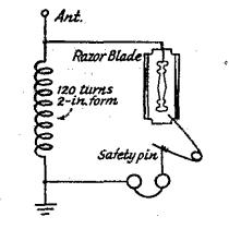
Further details on the foxhole radio sets now have been received from a correspondent in Italy. The razor blade and safety-pin detector is described as follows: “A station was found by moving the point of the safety pin, anchored at the other end, over the opposite end of the blade from where it is connected to the coil and antenna. The ‘phones are inserted between the pin and the grounded side of the coil.” He adds that “reception was very good.”

Finally, a letter appears in the October issue of QST from Justin Garton. No call sign is listed, but Garton’s address is shown as 448 Riverside Dr., New York, N.Y. Garton reports that the boys on the Anzio beachhead were able to receive Rome during the day and Nazi propaganda programs from Berlin at night. Garton also includes the following schematic:

1944FoxholeSchematicQST

I wasn’t able to find a call sign for either Kujanpaa or Garton. Since the Stray indicates that Kujanpaa was licensed but didn’t give his call, I’m guessing what happened was that he was licensed after Pearl Harbor and consequently did not receive a call sign. It’s possible that he received a call after the War, but I wasn’t able to find it. According to this enlistment record, one Toivo J. Kujanpaa of Massachusetts, born in 1910, enlisted on June 11, 1943. According to the Social Security Death Index, he was born on June 19, 1910, and died on January 6, 1991.  Its quite likely that he got his amateur operator license after Pearl Harbor but before enlisting a year and a half later.  With the wartime moratorium on station licenses, he would not have received a call sign, despite being licensed.

If you’re an ARRL member and logged into your account there, you can download the QST articles cited above at the following links:

And this June 1945 Stray submitted by W2MIB includes an alternative detector,

Update:  Gould’s book “All About Radio and Television” is now available for free download at AmericanRadioHistory.com.

Click Here For Today’s Ripley’s Believe It Or Not Cartoon


Mobile Wireless Goes To War: 1914

1914ArmyWirelessTruck

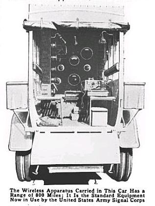
The Army Signal Corps truck-mounted wireless, as shown in Popular Mechanics, October, 1914.

A hundred years ago today, May 10, 1914, mobile wireless was about to become a reality for the U.S. Army, as reported in the Washington Herald of that day:

U. S. WIRELESS STATION
IS MOUNTED ON AUTO

Government Rushing Work on New
Portable Apparatus for Signal
Corps in Mexico.

A new wireless station mounted on a mortortruck. which is being constructed with all haste by the [U.S.] government in Mexico, was given a preliminary trial last night in which the operator was In easy communication with Key West and Philadelphia. The machine is to be used by the Signal Corps of the troops in Mexico.

The idea of a wireless station made portable by mounting on a motortruck, is original with the War Department and this machine which soon will be ready for active service is probably the only one of its kind in existence. The machine is constructed on a new design by Signal Corp engineers and has been assembled by the National Electric Company, work continuing In secret night and day.

A new “rapid transmitting panel” containing the latest improved wireless apparatus has been set about midway in a big six-cylinder White auto-truck, which carries in boxes at each side, a jointed portable aerial reaching 85 feet into the air when fully extended. The electric power for the wireless is furnished by the motor of the truck In direct connection with an electric generator, supplying enough current to light the mounted wireless room and run the instruments at their full capacity. The apparatus has a range of 400 to 800 miles in sending, and of nearly 2,500 miles In  receiving. The machine is for service at the army’s general headquarters giving the commander of forces easy communication with a fleet at sea, or with any of the small portable field instruments carried by sections of the Signal Corps.

In recent preliminary trials the machine was subjected to strict tests. As soon as the work reaches a satisfactory stage of completion field tests will be given and the possibilities of the equipment accurately determined. Quick shipment to Mexico will follow.

Click Here For Today’s Ripley’s Believe It Or Not Cartoon


Doing an FCC Ship Inspection

File:Denis Sullivan.jpg

Schooner Denis Sullivan. Wikipedia image. Michael Pereckas from Milwaukee, WI, USA [CC BY 2.0 

About 30 years ago, I got my FCC Commercial Second-Class Radiotelephone Operator’s License.  A few years later, the FCC consolidated the licenses, and it became the General Radiotelephone Operator’s License (GROL), and I was suddenly on equal footing with those who held the First Class license, for which I never got around to taking the test.  Other than the slight bragging rights associated with having such a license, I never made use of it until yesterday.

Last fall, I decided to post on my website the fact that I was duly licensed and qualified to conduct inspections of certain vessels on the Great Lakes.  I thought it might be an interesting diversion.  I guessed that if anyone called, it would be the owner of a small passenger vessel.

Last week, I got a call, but it wasn’t from the owner of a small vessel.  Instead, it was from the Captain of the Schooner Denis Sullivan, a 98-foot re-creation of a typical 19th century 3-masted Great Lakes schooner, owned and operated by Discovery World, a Milwaukee science museum.  So yesterday, I drove to Milwaukee and tested and signed off the vessel’s radio installation.  It did pass with flying colors, and I can personally attest to the safety of the radio installation.

My inspection was mostly limited to the VHF radio, power supply, and a visual inspection of the EPIRB.  I wasn’t able to do a full inspection of the MF-HF radio and other equipment, so my inspection is valid only for the Great Lakes.  If the ship is taken into international waters, which it has been in the past, it will need a more complete inspection, which is more readily done at a major port.

I encourage you to visit the website of Wisconsin’s official flagship to see this majestic ship.

I had to scrounge together some of the equipment I needed for the inspection, and would like to thank N0AIS and K0NY for graciously supplying some of the required gear.

Click Here For Today’s Ripley’s Believe It Or Not Cartoon


Herbert Hoover Ponders Deputizing Hams


Radio Fan Getting the Time and Weather Observations Over the Wireless.  It Will Not Be Long Before the Radiophone Will be One of the Necessities of the Home.  Richmond Times-Dispatch, April 23, 1922, page 3.

Radio Fan Getting the Time and Weather Observations Over the Wireless. It Will Not Be Long Before the Radiophone Will be One of the Necessities of the Home. Richmond Times-Dispatch, April 23, 1922, page 3.

92 years ago today, the Richmond Times-Dispatch of April 23, 1922, reported the possibility that amateur radio operators would serve as deputies of the Commerce Department in policing the airwaves. The paper reports that Commerce Secretary Herbert Hoover was favorably disposed to a recommendation that deputy radio inspectors be elected from the ranks of hams.  Once deputized, these inspectors would endeavor to secure strict observance of the radio communications laws.  If the law required compensation, then these deputies would serve for a payment of one dollar per year.

The paper pointed out that hams in the Richmond area had already voluntarily observed for a number of years rules of etiquette. For example, in Richmond, local stations had been observing a schedule described thus:

the hours from 6 A.M. to 6 P.M. as “free air,” that is, communications of any kind; 6 P.M. to 7:30 P.M., local communication; 7:30 to 11 P.M., standby for broadcast; 11 P.M. and on, long-distance amateur communication.

The article went on to include the following praise: “The average amateur works in a highly technical manner, particularly if he is a member of the American Radio Relay League, an organization of amateurs stretching all over the United States and permitting of constant communication at all times and places.” It concludes by stating that the “amateur promises to be the backbone of our national system of popular radio, now springing into being.”


The Flame Audion

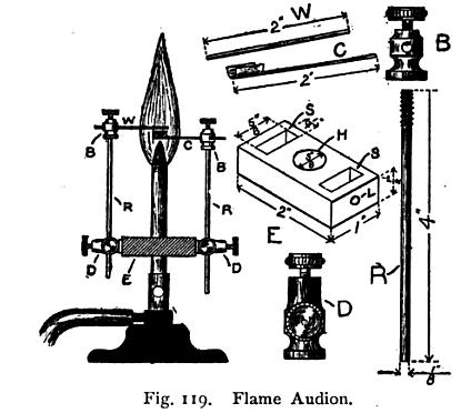
One interesting footnote in Radio History can be found in Alfred Powell Morgan’s 1914 book Wireless Telegraph Construction for Amateurs. This is the Flame Audion detector, shown below:

FlameAudion

Morgan describes it thus:

The simple but sensitive form of detector illustrated in Fig. 119 is not of practical value for commercial work, but is very interesting as the progenitor of the audion, and provides a good field for amateur investigation. Its only drawback is that the gas flame is very difficult to keep steady and every flicker registers as a sound in the telephone receivers.

A Bunsen burner using coal gas furnishes the flame, and a salt of an alkaline metal heated in the flame, the ions. The hydroxides of csesium, potassium and sodium give the best results in the order named.

The salt is contained in a piece of trough-shaped platinum foil, about 3/8 inch long and 1/16 inch wide. This trough is made the cathode or negative of the telephone circuit and placed in the outer oxidizing flame just above its juncture with the interior reducing flame and must be kept incandescent. The upper electrode .or anode is a piece of platinum wire about  1/16 inch above the trough.

The arrangement and construction of the detector is clearly indicated by the drawing so that it is unnecessary to go into details. The block, E which fits on the tube of the Bunsen burner, is made of fiber. Two double binding posts, D, are fastened to E to support the rods, R, which are fitted at the tops with binding posts, B, into which the electrodes may be clamped.

Twelve dry cells are connected with a multiple point switch so that an electromotive force of 6-18 volts, varying in steps of one cell at a time, may be secured. The flame is best provided with a mica chimney to protect it from drafts. By keeping plenty of salt in the trough and carefully adjusting the voltage, this detector may be made marvelously sensitive.

This type of detector was the inspiration for the Audion tube. The effect was discovered by the Audion’s inventor, Dr. Lee DeForest, in 1903. DeForest writes in 1947 about this discovery:

I used a Bunsen burner, locating within the flame two platinum electrodes, one of which was connected through the telephone receiver to a dry battery, and thence to the other platinum electode. I enriched the flame with sodium, or common salt.

I then found that when the electrodes were properly located in the gas flame the signals from my spark transmitter were distinctly audible in the telephone receiver. I made countless experiments with this phenomenon; and to prove definitely that the effect was not acoustic but electrical, I connected one of the flame electrodes to my antenna, the other to the ground, and actually obtained wireless signals from ships in New York Harbor.

Radio-Craft, January, 1947

deforestdiagram

DeForest’s Diagram of the Flame Audion Circuit

DeForest applied for a patent in 1905, and was issued U.S. Patent 979275 for the flame detector in 1910.

DeForest wrote about the flame audion himself a number of times. For example, see his articles in Western Electrician, November 3, 1906; the February, 1916, edition of Popular Mechanics; the January, 1947, issue of Radio-Craft.

He wrote a more complete scientific paper which was published in the Transactions of the American Institute of Electrical Engineers in 1906.

DeForest is occasionally criticized for not really understanding what was going on inside the triode. This criticism isn’t really fair. It was later discoverd that the Audion acted as an amplifier. It was quite imperfect as an amplifying tube, because it did not have a complete vacuum. But from reading DeForest’s writings, it is clear that he never intended to invent an amplifying tube. He was working on a detector, and the ionized gas within the tube (which wouldn’t have been there if it had been a true vacuum tube) was responsible for this capability. The amplifying ability was, indeed, a lucky accidental discovery. But particularly looking over the 1906 paper, it’s clear that DeForest was an extremely gifted engineer, and he is worthy of the credit he has received for his advancement of radio in the early years.

It seems to me that students looking for an interesting science fair project might be inspired by DeForest’s work. It combines both fire and electricity. Since it had no reasonable commercial use in the early 1900’s, there was no good reason for scientists to pursue it. But it seems to me that interesting things might be going on inside that flame.

DeForest used platinum wire, which is rather expensive. On the other hand, the cost isn’t entirely out of line. For about $20, you can buy enough Platinum Wire to construct the detector. Platinum foil would be prohibitively expensive, but there doesn’t seem to be any reason why the salt needs to be contained by the platinum. It seems to me that two platinum wire electrodes could be used. And while DeForest used platinum, there doesn’t seem to be any evidence that he experimented with other metals. Would copper perform the same function?

The flame audion was used as a radio detector by DeForest. But earlier scientists had shown that the flame would conduct electricity, a fact that is obvious from the flow of current through the gap. What flames provide better conductivity? Salt is added presumably because it ionizes better than just the fuel and air alone. It would be a relatively simple matter to measure the conductivity of different ionized materials.  Variations in the flame can be heard in the headphones, so for the purpose of making a sensitive radio detector, it’s probably necessary to have a very constant flame.  But for many applications, it seems to me that an ordinary candle would suffice.

(For more science project ideas, see my review of the book Radio Science for the Radio Amateur.)


More Century Old Radio

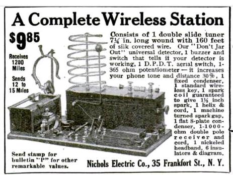
April1914PMwirelessThe  April 1914 edition of Popular Mechanics includes this Complete Wireless Station for $9.85 from the Nichols Electric Company of 35 Frankfort Street, New York.  That address had housed the “Clean and Ready Company” in 1893.  It now appears to be part of the campus of Pace University, next to the Manhattan entrance to the Brooklyn Bridge.

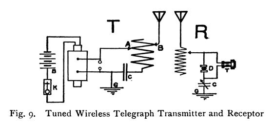
According to this inflation calculator, the $9.85 cost would be $232.75 in today’s dollars. To look at it another way, that would cost ten silver dollars, or about ten ounces of silver, which would be worth about $200 today. This apparatus seems very similar to one described by Alfred Powell Morgan in his book published in the same year, Wireless Telegraph Construction for Amateurs,  with two exceptions: This set doesn’t appear to have the variable condenser shown in Morgan’s schematic, below.  On the other hand, this set includes a knife switch in order to use the same antenna for both transmitting and receiving.

1914 Morgan Schematic

1914 Morgan Schematic

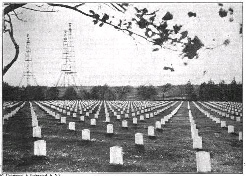
The receiver is a simple crystal set, billed as being able to receive 1200 miles. I suspect this figure involves a bit of hyperbole, but I suppose with a good antenna and good conditions, it might be possible to occasionally log stations such as NAA, transmitting time and weather from massive towers overlooking Arlington National Cemetery, shown here in 1922.

NAA Towers 1922

NAA Radio Towers, Overlooking Arlington Cemetery. Radio World, November 25, 1922.


The transmitter is billed as being capable of transmitting 12-15 miles. The ad doesn’t mention anything about a license. Licenses had been required since 1912, but it’s quite likely that the owner of this set wouldn’t have bothered. In fact, it’s unlikely that he would have been able to receive a license after explaining to the radio inspector what kind of equipment he was using.

The license requirements are explained in Morgan’s book.  Morgan explains:

An amateur may not use transmitting apparatus which is sufficiently powerful to send radio signals across any of the boundaries of the state in which he is located and which can be detected by a sensitive receiving set located just beyond the state boundary, nor can he use apparatus which is powerful enough to interfere with the reception of signals by others from beyond the state boundaries unless he has a license….

In other words if the amateur possesses a receiving outfit only which is in working order or if he has both transmitter and receptor and the.former is not powerful enough to send signals out of the state in which he fives, or to interfere with the reception of messages by another when the messages come from beyond the state boundary a license is unnecessary.
This is of course somewhat unfair for those living near the center of large states for they may operate almost as they please with ordinary instruments with no fear of the signals going beyond the border, while those living within a few miles of another state must secure a license.

Morgan goes on to explain why this set probably wouldn’t qualify for a license:

The law also says that the transmitting wave must be pure, and must be sharply tuned, which means that the wave must be of one length and not, as is very often the case, composed of two or more waves of different lengths.

In order to comply with this restriction, the use of an oscillation helix or loosely coupled helix is necessary. A rotary or quenched gap is also necessary in place of the ordinary spark gap.

The transmitter shown here fails in two regards. First of all, there’s no way of quenching the spark, although I suspect if it was run on batteries, that wouldn’t be much of a problem. The main problem is that the “helix” is basically a tapped autotransformer, and it will probably radiate quite well on at least two wavelengths. In addition, the signal from a transmitter like this is going to have a very wide signal.

I suppose, with a good antenna, this transmitter might be heard 12-15 miles away. But if the owner was more than 15 miles from the state line, it would appear that he could use this without fear of the radio inspector, as long as a licensed station didn’t complain of interference.

By the way, if the name Alfred Powell Morgan rings a bell, you’ll recall why when you visit my Alfred Powell Morgan page.


Radio and Timekeeping a Century Ago

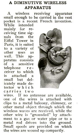
1914PortableRxThe April 1914 issue of Popular Mechanics includes this interesting portable zero-tube radio.  It appears to be a crystal set consisting of a detector mounted directly to the headphone, with two wires for clipping to a convenient antenna and ground connection.

This particular receiver is billed as being for receiving time signals from the Eiffel Tower, which had begun on May 23, 1910.  The station, FL, was operated by the French
Bureau des Longitudes, and transmitted time signals from the Paris Observatory. It operated on 2000 Meters (150 kHz) with a spark transmitter of about 40-50 kW. Service even continued during the war, which began for France about three months after this magazine was published.

Despite the apparent lack of any tuner, a crystal set such as this ought to have been able to receive the signal for quite a distance from Paris. As you can see, the two wires had clips for attaching to any suitable antenna and ground. The signal from the powerful station was so reliable that a guide to receiving the signals, published by the Bureau of Longitude in 1913, was translated and published in English in 1915. The translation is available to read at Google Books.

The original 1913 edition, Réception des signaux radiotélégraphiques transmis par la Tour Eiffel, is also available online.

Any doubts about whether a crystal set would be able to receive the powerful signal should be put to rest by the mere fact that this guide book was published in England. The guide states that the “energy radiated by the Eiffel Tower Station in transmitting signals is great enough to permit the use of receiving aerials of reduced height and dimensions throughout the whole of France and in the French possessions in North Africa.”

Station FL transmitted the exact time nightly at 11:45, 11:47, and 11:49 PM.  And it seems quite likely that the little pocket receiver shown here would have been suitable for receiving it throughout much of France.

The Eiffel Tower time signals had the very practical purpose of an indispensable aid to navigation. There are many ways by which one can determine latitude. But longitude depends on knowing the exact time at a fixed location on Earth, and then comparing that to the local time. One early method of determining the exact time was by observing the moons of Juipter.  Good chronometers largely solved the problem of having to go to these lengths, but there was still the matter of having to periodically set the chronometer. And time signals such as those provided by the Eiffel Tower greatly simplified the process.  A pocket sized receiver such as the one shown here would have been a most useful accessory.


Accessories for the Baofeng UV-5R

UV-5RI have had some comments wondering what accessories they should get with a handheld such as the Baofeng UV-5R. In general, you don’t need to buy anything else. You can use the radio out of the box, although some of the following items will make the radio more convenient or useful.

Programming Cable

None of the items on this page are essential, although many of them are nice to have. The one item that is almost essential is the programming cable. It is possible to do most of the programming directly from the radio, but it can be quite cumbersome. It’s much more convenient to use your computer to program the radio, and to do so, you’ll need the programming cable. In addition, you’ll need to install two pieces of software. The first software you’ll need will be the driver for the cable, so that your computer will “see” the cable plugged in to the USB port. That software is included in a little disk that comes with the cable. Once that’s done, you’ll need separate software to allow your computer to “talk” to the radio. The best I’ve found is CHIRP, which is available as a free download.

The current Amazon price for the cable is shown below:

Speaker Mike

My UV-5R came with a small combination earphone/microphone. You wear the earphone in your ear, and there is a small microphone/push-to-talk button the clips on to your shirt. I rarely use any kind of external microphone, but if I wanted one, one like the following would be much more convenient. It doubles as a speaker, which could be useful in a noisy environment.

Extra Battery

An extra battery can be useful. The following batteries can be charging separately while the radio is in use. You simply drop them into the charger that came with the radio. That way, you’ll always have a spare available. Note, different sub-models have different batteries, so look at the description carefully to make sure you get the right one. On a positive note, if you get the wrong one, they are all the same voltage, and you can usually make the “wrong” battery fit by carefully cutting away some of the plastic. But it’s best just to get the right one in the first place.

Alkaline Battery Holders

It will cost you more to use alkaline batteries, but this can be a good option to have available. If your power is out, you might still have alkaline batteries available. You can buy them anywhere, such as grocery stores and even toy stores. In an emergency, this can give you much needed flexibility. The following holder uses AAA batteries.

Of course, you can buy batteries anywhere, but if you’re making an Amazon purchase and/or you’re an Amazon Prime member, just buying them from Amazon can be very convenient and economical:

Battery Eliminator

It is possible to plug the radio into the charger and charge it while you’re operating. In the case of the UV-5R, however, this is somewhat inconvenient, since the radio uses a drop-in charger. It’s also not the best way of doing things, since the batteries are still in the circuit, even though they are not in use. A better method is to run the radio directly off a power supply, without using any batteries at all. To do that, you’ll need the following accessory. As you can see, this plugs into a car lighter socket.

If you want to use the radio at home from AC current, you’ll need a power supply to plug this adapter into. You’ll need a power supply that puts out at least three amps, such as the following one:

Car Charger

To charge the radio in your car, you’ll need the following cord. This plugs in to the drop-in charger that comes with the radio, and you use it in place of the AC adapter.

Replacement Antenna

The antenna that comes with the UV-5R is not very efficient. It’s not designed to be efficient–it’s designed to be a convenient length. And for most uses, an efficient antenna is not necessary. But you might want to have a better antenna available, that provides a little bit of gain, rather than the negative gain from the supplied antenna. When you buy an antenna, make sure that it has a “reverse SMA connector” such as the following:

External Antenna

If you’re going to use the radio at home or in your car, then it will work much more efficiently with an external antenna. Either buy one of the following, with the “reverse SMA connector” already installed, or get the adapter shown below.

Note:  The UV-5R’s receiver is very sensitive to overload, so if you use an antenna that’s “too good”, you can actually cause more problems than you solve.  But for many applications, an external antenna can be extremely useful.

Antenna Adapter

If you already have an antenna, or if you’r buying a new one, it probably has a “PL-259 connector”. If so, you’ll need an adapter to connect it to the radio. You’ll need this cable:

Even if you plan to make your own antenna, you should get this cable. The PL-259 connector is relatively easy to work with, but the SMA connector is virtually impossible to install yourself without special tools. This cable will allow you to use an antenna with the PL-259.

You might be able to find a similar adapter that does not include a section of cable. While such an adapter will certainly work, it’s generally not a good idea. The cable on the adpater shown above is extremely flexible, and much lighter than the cable on most antennas. Therefore, it will cause little mechanical stress to the connector on the radio. Attaching a rigid cable directly to the radio will probably cause the connector to eventually break.

When you get this adapter, you will notice that it’s somewhat difficult to screw onto the radio. Because it’s a “reverse” connector, you’ll find that you need to turn the radio rather than the cable. In other words, you need to “screw in the radio” instead of “screwing in the connector” as you might expect. The radio is small enough that this doesn’t pose a problem, but it does take a bit of getting used to.