 Sixty years ago, the December 1962 issue of Radio-Electronics showed how to make this converter to listen to TV sound in high fidelity. Of course, one way to do it would be to simply tap into the audio detector of the TV set, and feed that to the hi fi. But that, according to the article, left a lot to be desired, since it usually resulted in buzz, distortion, and background noise that would stand out like a sore thumb in a good audio system.
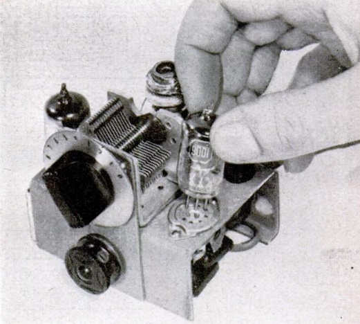
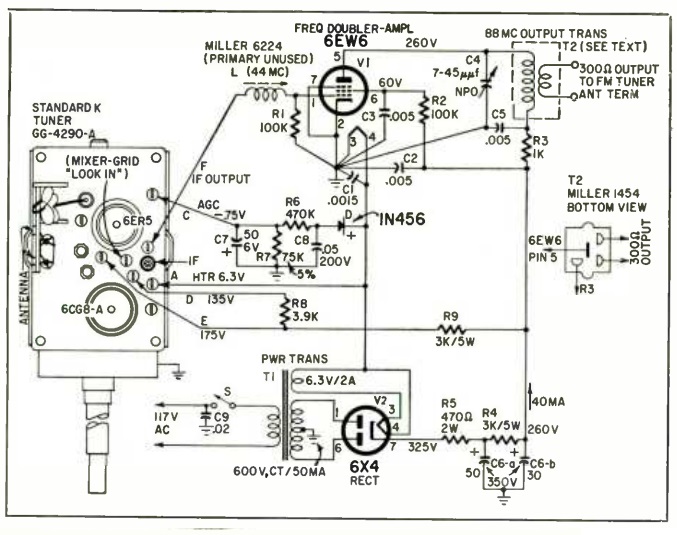
The solution was to build this converter, and feed it into the FM receiver. And most of the circuit was available off the shelf, in the form of the TV tuner. When these needed repiar, the local repairman typically removed them and traded it in for a rebuilt unit, making the rebuilt units readily available. Ads in the same issue of the magazine showed complete tuners for about $9.95. This tuner had a 44 MHz IF, meaning that the sound IF was 41.25 MHz.
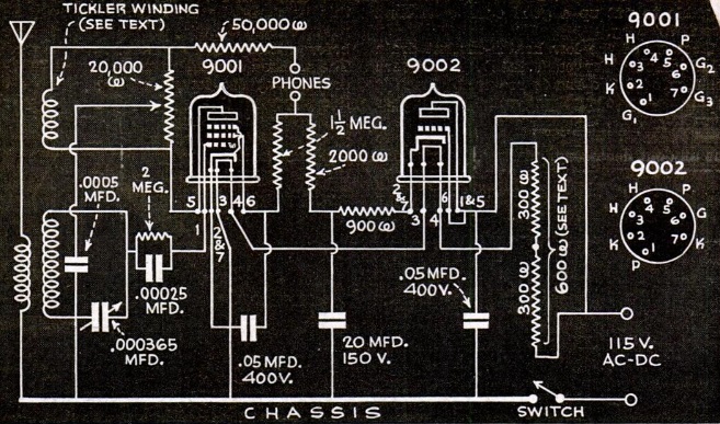
To be able to tune this in on an FM receiver, the builder first tweaked the slugs and trimmers inside the tuner to bring it up to 44 MHz. This was fed into an amplifier-doubler, with the grid tuned to 44 MHz and the plate tuned to 88 MHz. The result was that the output showed up on 88 MHz, at the bottom of the FM dial.
With a reasonably good antenna, the little converter was said to provide good sound reception for stations up to 75 miles away.
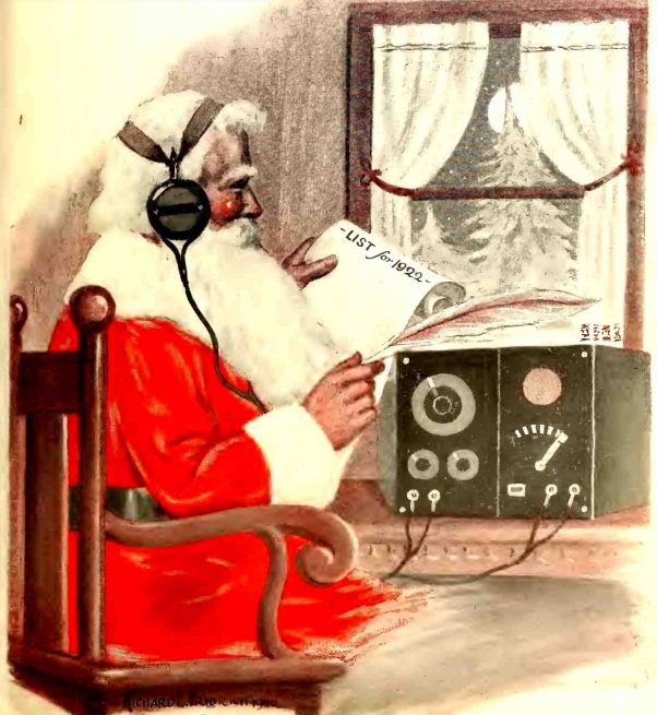 A hundred years ago, Santa was getting ready for Christmas. When it came time to make his list and check it twice, he made sure he got the most current information by radio, as shown in this illustration on the cover of the December 1922 issue of Radio Age.
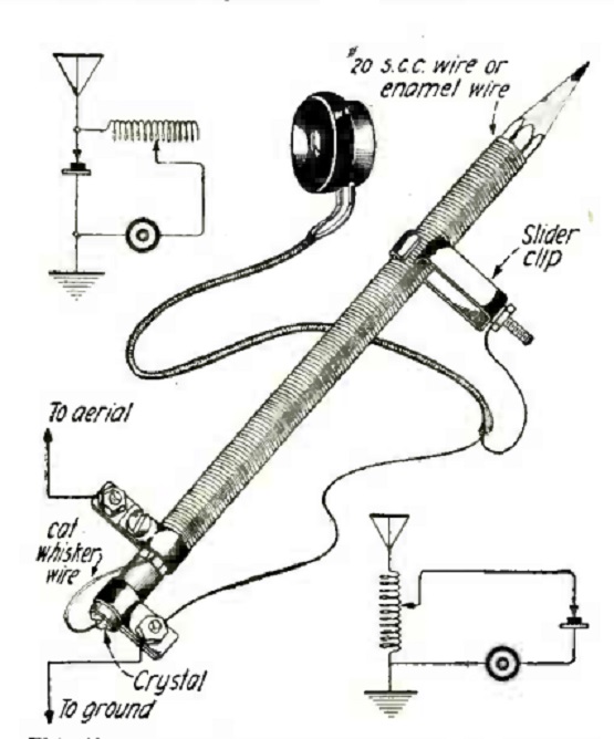
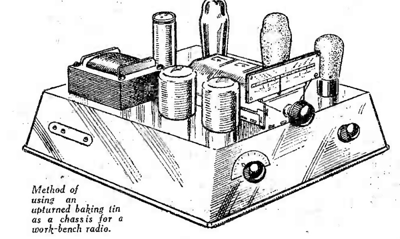
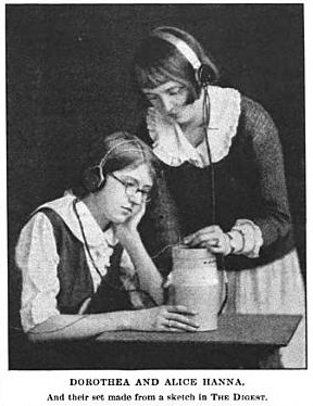 One of the ads mentions the “Literary Digest Hookup,” which is probably the set shown here, which