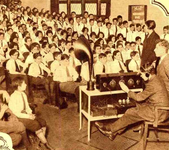
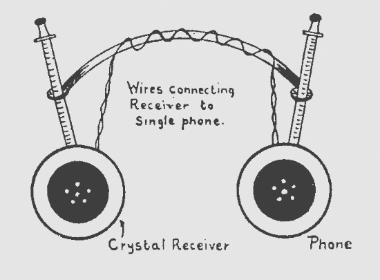
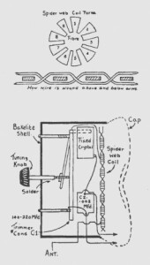
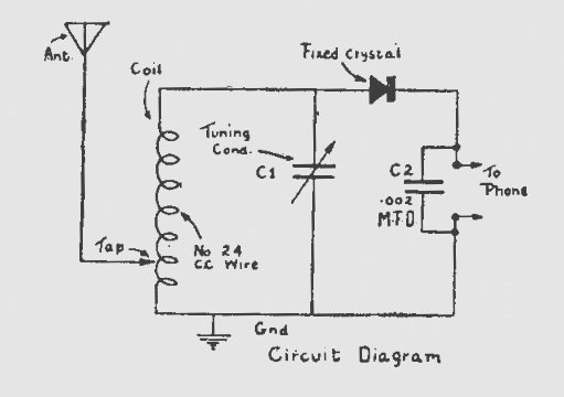
Category Archives: Radio history

1962 TV Sound Tuner

1962DecRadioElec2Sixty years ago, the December 1962 issue of Radio-Electronics showed how to make this converter to listen to TV sound in high fidelity. Of course, one way to do it would be to simply tap into the audio detector of the TV set, and feed that to the hi fi. But that, according to the article, left a lot to be desired, since it usually resulted in buzz, distortion, and background noise that would stand out like a sore thumb in a good audio system.

The solution was to build this converter, and feed it into the FM receiver. And most of the circuit was available off the shelf, in the form of the TV tuner. When these needed repiar, the local repairman typically removed them and traded it in for a rebuilt unit, making the rebuilt units readily available. Ads in the same issue of the magazine showed complete tuners for about $9.95. This tuner had a 44 MHz IF, meaning that the sound IF was 41.25 MHz.

To be able to tune this in on an FM receiver, the builder first tweaked the slugs and trimmers inside the tuner to bring it up to 44 MHz. This was fed into an amplifier-doubler, with the grid tuned to 44 MHz and the plate tuned to 88 MHz. The result was that the output showed up on 88 MHz, at the bottom of the FM dial.

With a reasonably good antenna, the little converter was said to provide good sound reception for stations up to 75 miles away.

1962DecRadioElec3


1947 RCA Victor

1947Dec15LifeSeventy-five years ago today, the December 15, 1947, issue of Life magazine carried this RCA Victor ad showing some of the company’s offerings for the Christmas season.

It featured first the model 63E phonograph, which featured both plenty of volume for dancing, but also fine tone for the more serious music.

The handsome model 68R3 radio tuned in both AM and FM bands, and included the ability to plug in a record player.

Finally, the model 75X11 was only 10 inches long, and the dial face and pointer glowed when the set was on, making tuning of the AM band easy. It also came as model 75X12 in ivory-finish plastic.


1922 Simplest Radio Outfit

1922DecSciInvShown here from a hundred years ago is the 7th place winner in the “Simplest Radio Outfit Contest” shown in the December 1922 issue of Science and Invention magazine.

The self-explanatory set was designed by one George Goga, who took home a $25 prize for his entry. The magazine noted that almost all of the parts, with the exception of the headphone, could be found ayt no cost in the home junk box. A pencil forms the chassis. The eraser is removed and a galena crystal inserted in its place. The coil is wound along the pencil, with about 3/16″ of the insulation cleaned off so that the slider can contact the wire.

Mr. Goga reported that he lived several miles from station KDKA, and was able to pull in concerts clearly with a 50 foot long antenna 10 feet high.


1942 Miniature 2 Tube AC-DC Receiver

1942DecPS1Eighty years ago this month, the December 1942 issue of Popular Science showed how to put together this two-tube AC-DC set. The miniature set used two midget tubes, types 9001 and 9002. The 9002 pentode served as a sensitive detector, and the 9001 triode was used as a rectifier.

The filaments were wired in series, and since they required a 600 ohm dropping resistor, not one but two “curtain burner” cords were used, wired in series.

With a short antenna lying along the floor, the set could pull in local stations with good selectivity. Out in the country with a 75 foot antenna, it boasted a range of 600 miles.

1942DecPS2


Tube Aging, 1947

1947DecRadioNewsThese workers at Hytron‘s plant in Newburyport, Mass., are aging tubes to ensure long life. An incandescent lamp is wired in series with each tube element to limit current. This process of seasoning and degasifying the tubes ensures more uniform tubes.

The photo appeared on the cover of Radio News, December 1947.


Electronics Numbers Quiz

1962DecPEquizToday’s quiz comes from the December 1962 issue of Popular Electronics. You have to match up the number associated with each diagram.  Answers will appear here tomorrow.


1942 Expedient Chassis

1942DecPracWirThe December 1942 issue of the British Practical Wireless carries this self-explanatory hint sent in to the magazine by one J.M. Firth of Beckenham. He noted that there was a great shortage of aluminum and sheet iron for making chasses for radios. Quite possibly to Mrs. Firth’s chagrin, he found a suitable replacement in the kitchen in the form of a tinplate baking tin. He noted that the pan would take solder easily.


1947 Five-Tube Radio Kit

Screenshot 2022-11-18 12.51.08 PMThere’s a reason why this young woman seems particularly cheerful about pulling in a station on her broadcast radio. It’s because she put the radio together herself from a kit.

The kit is described in the December 1947 issue of Popular Mechanics, and from the description, it sounds like an “All American Five” of the type manufactured by the millions. Curiously, though, the magazine doesn’t mention the source.  If any of our readers can identify the brand of this kid, please let us know.


1922 British Frame Antenna & Variable Capacitor

Screenshot 2022-11-18 10.09.13 AMA hundred years ago, this young British woman was pulling in some signals from her garden at 1276 Leeds Road, Bradford.  She is undoubtedly the daughter of one Mr. C.R. Land, who constructed the set and sent the picture to Practical Wireless, where it appeared in the November 1922 issue.

The issue also showed an interesting method of constructing a variable capacitor, as shown below.  The magazine noted that they could be expensive and difficult to make, but this version was relatively easy to construct at home.  It consisted of two sheets of zinc carefully rolled into tubes and soldered together.  The dielectric consisted of waxed paper.

Screenshot 2022-11-18 10.15.57 AM


Some links on this site are affiliate links, meaning that this site earns a small commission if you make a purchase after using the link.

1962 Westinghouse Saranade Part 15 Doll

1962NovPM3Sixty years ago, the editors of Popular Mechanics did some testing of the latest toy offerings to see how they would hold up to rough use. The results appeared in the November 1962 issue.

One of the most intriguing toys they tested was the $40 Saranade doll from Westinghouse, shown above. But Saranade was much more than a doll. She was what one site called a “creepy Part 15 doll.” She came complete with her own record player (which played all speeds, 78 through 16 RPM). But it wasn’t just any record player. The player had a “DOLL – PHONO” switch. In the phono position, it played just like any other record player. But in the doll position, the speaker cut out, and the sound came out of a speaker strategically placed in the doll’s stomach.

The player had a one-tube amplifier inside, and when the switch was flipped, it became a transmitter on 180 kHz, in the Part 15 Lowfer band.  In fact, it’s the only commercial product that I can think of that took advantage of this band. The doll contained a receiver, apparently transistorized, tuned to this signal. The doll contained neither tuning nor volume control. Fine tuning was accomplished with a control on the record player.

As with other toys reviewed, both the doll and record player survived drop tests, and were pronounced by the editors to be suitable for rough service at the hands of kids. Other items reviewed were the megaphone and perfume kit shown below, as well as the General Electric model EF 150 5 transistor shortwave receiver kit, which retailed for $29.95.

1962NovPMmegaphone1962NovPMperfume1962NovPM