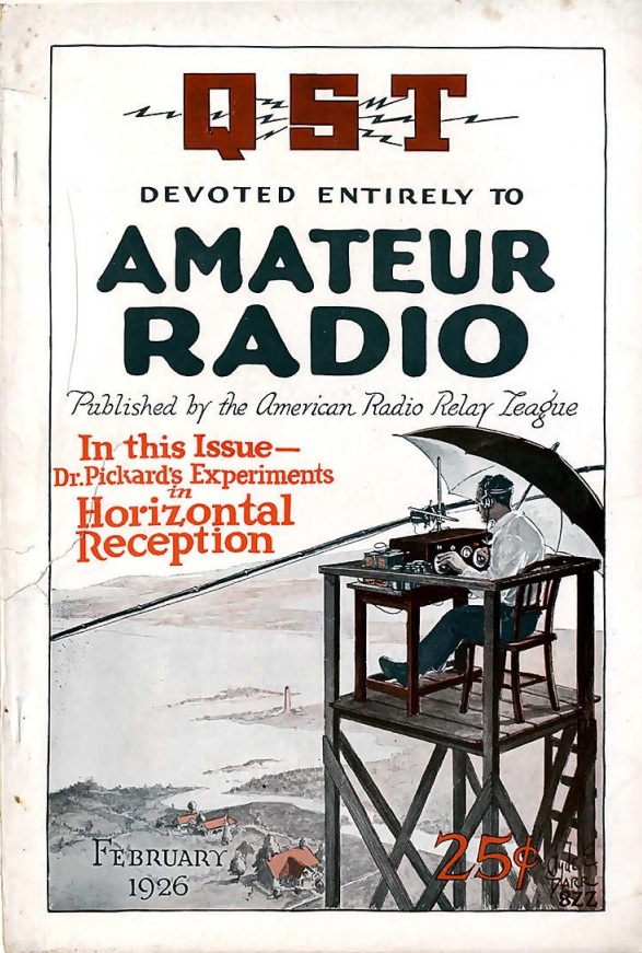
Category Archives: Radio history

1955 British Radio-Phono

Screenshot 2025-02-14 10.13.11 AMThe excitement is palpable in this image from the cover of the March 1955 issue of Practical Wireless. It looks like they’re simply listening to a record on their radiogram (what we would call a radio-phono on this side of the Pond). But one of them actually built the set according to plans in the magazine.

The set was said to be a selective and sensitive station getter, and had a tolerably high standard of reproduction for both the wireless and the gramophone. The March issue started the construction plans for the eight-tube set, to be continued in the April issue.


Radio in Seward, Alaska, 1925

Screenshot 2025-03-07 11.38.13 AMThis ad for dealer Cal M. Brosius appeared a hundred years ago today in the March 9, 1925, issue of the Seward (AK) Daily Gateway. There were no broadcast stations in Alaska, so a crystal set probably wouldn’t do you much good. But if you had a superheterodyne, there would be a lot to listen to at night. This dealer included a list of stations that had been received in Seward on the Radiola Super VIII or Super Heterodyne.  They included stations on the east coast, as well as stations in western Canada and the U.S. west coast.

But it wouldn’t be cheap.  The Super Heterodyne would set you back $285, and the Super VIII would be $425.  When adjusted for inflation, that works out to $5233 and $7804.


Scouts Build Radio, 1925

1925MarBLOne hundred years ago this month, the March 1925 issue of Boys’ Life showed Eagle Scouts Andrew S. Bostwick and H.I. Swanson, both of Troop 711, Brooklyn, at the controls of the radio they had built.  The magazine reported that they picked up 150 stations during the course of one evening.

Perhaps the duo inspired some scouts to build the two-tube receiver described in the same issue of the magazine:

1925MarBL2


1965 Light Beam Communicator

Screenshot 2025-02-13 11.35.20 AMThe young man in this drawing is now a senior citizen, but in 1965, he was taking part in the school science fair, using a project shown in the Winter 1965 issue of Elementary Electronics. He was communicating with a light beam, with a rudimentary setup consisting of two audio amplifiers. The output of one of them was hooked directly to a light bulb (in series with a 3 volt battery), and the input of the other one was hooked to a photocell.

According to the article, this unit was good for demonstration purposes only, and was only capable of a couple of feet. I’m surprised that they are so conservative in their estimate, since I made virtually the same setup when I was a kid, and it traversed the length of the house without much difficulty.

The only difference in my version was the addition of a transformer to the output of the first amplifier. The primary was hooked to the amp, and the secondary was wired in series with the battery. I used a flashlight, and just sandwiched two pieces of foil, insulated by cardboard, between the lamp and the battery terminal. I suspect my use of a flashlight, complete with its parabolic reflector, was probably an important factor in my success.

Screenshot 2025-02-13 11.37.27 AM


1940 Cane/Seat/Radio

1940MarPSEighty-five years ago, this no-nonsense outdoorswoman is enjoying a hike, but when she stops to rest, she can listen to a favorite program on this combination cane/seat/radio described in the March 1940 issue of Popular Science.

One HY115 tube served as a regenerative detector, with a second serving as AF amplifier.  A final HY125 audio stage powered the headphones.  The cane itself could serve as an antenna, or a convenient fence wire could be used.

As with everything, cane-seats can still be found on Amazon.  The exact instructions for mounting a radio will differ, but we’re confident that our readers can figure it out.

1940MarPS2


Some links on this page are affiliate links, meaning that this site earns a small commission if you make a purchase after using the link.

Charging the Battery With Your Toaster

1925MarPS1If you were one of the growing number of Americans who owned a radio 100 years ago, the cost of batteries would soon become a concern, and you would be thinking of ways to run the radio from your lighting current.

In many large cities, the power company supplied 110 volts direct current, and if that was your situation, the March 1925 issue of Popular Science showed you how to power the radio.  Even though the power was DC, the generators down at the power plant generated a lot of ripple, and if you just ran the radio straight from the line, the result would be a loud high pitched whine.  So the filtering arrangement above could be used.

1925MarPS2For the filaments, since you already had a battery, you could just use that, but then recharge it with 110 volts DC, as shown here.  To drop the voltage, you would start with a 60 watt lightbulb in series.  But to finish the job, you would want to lower the current, which meant putting the toaster in series.

If you weren’t sure about the polarity, you could run the simple test below:

1925MarPS3


Taking Radio on the Road, 1925

1925FebWirelessMagOne hundred years ago, an entrepreneurial radio dealer in Horsham, England, noticed that interest in wireless was lagging in nearby villages. He took it upon himself, therefore, to equip a motor van with a complete receiving set an hit the road. He paid periodical visits to enable the inhabitants to enjoy a wireless concert, and to bring to their attention the fact that his firm could sell them a set of their own.

In this picture, in the February 1925 issue of Wireless magazine, and it is noted that great pleasure is written upon the faces of the children listening here.


1925 Telemedicine

1925FebSciInvA hundred years ago this month, the cover of the February 1925 issue of Science and Invention gives Hugo Gernsback‘s vision of what telemedicine would look like. Of course, the word “telemedicine” hadn’t been coined yet, but the concept is there: “The doctor of the future, by means of this instrument, will be able to feel his patient, as it were, at a distance. The doctor manipulates his controls, which are then manipulated at the patient s room in exactly the same manner. The doctor sees what is going on in the patient’s room by meads of a television screen.”

The device did have a name, the “teledactyl.” That’s not a type of dinosaur, but instead means that it could feel at a distance.


Loop Antennas, 1940

1940FebNRNEighty-five years ago, this radio listener is showing off her RCA receiver. More specifically, she is showing the loop antenna mounted on the back, manufactured by Consolidated Wire and Associated Corporations. She is on the cover of the February 1940 issue of National Radio News, which devotes several pages to the use of such antennas.

If you see some buyer’s remorse in her eyes, it’s possibly because the small antenna doesn’t work as well as the old aerial that was previously connected to the set.  If the serviceman was approached by a customer wanting the added portability of such an antenna, it was recommended that they explain the shortcomings. As opposed to a longer antenna, fewer stations could be pulled in. But if the receiver was fairly sensitive, the strong local stations could be heard. If the receiver covered the shortwaves, the customer would need to be told that reception would be severely limited.


1955 Two Meter Transceiver

1955FebPM1Seventy years ago this month, the February 1955 issue of Popular Mechanics showed how to build this transceiver for the two-meter ham band. The heart of the four-tube set was a 6C4 tube which served as superregenerative detector on receive, and as a Colpitts oscillator on transmit. Since the tuning circuit was in common with both circuits, there was no problem with tracking, but care had to be taken to keep the entire transmitted signal within the band.

1955FebPM2