A hundred years ago today, this Montana newspaper explains how mariners are now able to receive weather reports from the towers of the powerful radio station NAA in Virginia.

A hundred years ago today, this Montana newspaper explains how mariners are now able to receive weather reports from the towers of the powerful radio station NAA in Virginia.
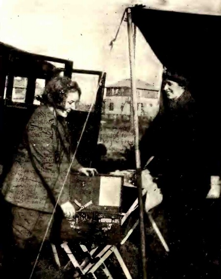
In 1924, it was going to be a radio summer. This picture, from the May 1924 issue of Radio Age, shows two motor tourists who made the radio receiver an important part of their roadside camp. The magazine points out that such portable sets are easily made or purchased.
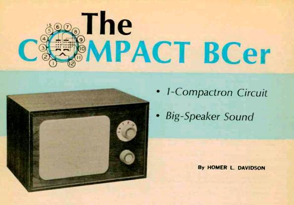 Fifty years ago, the vacuum tube was still king, although its days were coming to an end. The September 1964 issue of Electronics Illustrated contained several construction projects, most of which relied on tubes. The Micron Electron Tube Company advertised a few dozen common tubes for 37 cents each. Other tubes were available at reasonable prices. For example, hams looking for finals for their transmitter could find an 807 for a dollar, or a 6146 for $2.45.
Some transistor gear was starting to show up, but it was pricey. E.F. Johnson advertised two transistorized CB handheld radios. The 100 milliwatt version sold for $109.50, and the 1.5 watt version commanded $129.50.
The construction projects included a CB preamplifier and calibrator for tuning 11 meters on a shortwave receiver. This article bears the byline of prolific author Len Buckwalter
For hams, the magazine featured a transmitter for 80 and 40 meters, which the article claimed could be built for five dollars. It used a 6V6GT and a 5U4G rectifier, both of which were on the 37 cent list.
And, as fitting for this site, the magazine featured the one-tube AM radio shown above, which used a 6AL11 dual pentode. Half the tube was used as a regenerative detector, the other half being an audio amp which would deliver a full two watts to the speaker. According to the text, the circuit “has only one tube but in terms of performance it’s a mighty far cry from that one-tube job of 30 or more years ago,” with sensitivity and tone that will surprise you.
What’s intriguing about this project is that it’s probably one of the last times that an electronics magazine would feature an article on how to build a standard AM radio that appears to be designed for everyday use. The 1964 Radio Shack catalog included an “all American five” AM radio for only $7.95, so even the most frugal builder would probably save very little by building his own.
Len Buckwalter seems to still be around. He is listed as a founder of publisher avionics.com of Leesburg, Virginia. It appears that he let his ham license lapse at some point, but he appears to be currently licensed as KK4GJX, which is listed as being issued in 2012. According to a biography, he graduated from college in 1951, which would mean that he’s now about 85 years old.
If you’re interested in building this radio, most of the parts should be readily obtainable. Antique Electronics Supply is probably the best supplier for the power transformer. They don’t carry the tube, but it can be found on eBay. On another post, I have links to suppliers where you can find most of the other parts.
References
Len Buckwalter at semiconductormuseum.com
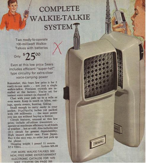
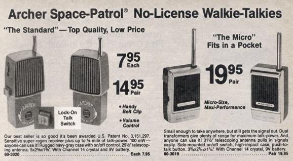
Like many aspiring young hams, I got my start in two-way radio with a set of walkie-talkies not unlike this set shown on page 561 of the 1969 Sears Christmas Catalog.
My set was a different brand, but quite similar to this set and millions of others like it. They all consisted of a crystal-controlled transmitter, usually on CB channel 14, along with a superregenerative receiver. The receivers on these sets were so wide that they could hear all 23 channels simultaneously, which meant that I could hear local CB’ers, as well as communicate with these and other toy walkie-talkies. And the superregenerative receiver meant that when a signal was not being received, the radio put out a constant rushing sound, undoubtedly to the great annoyance of millions of parents.
Despite hearing CB’ers, and despite valiant efforts on my part involving various attempts at external antennas, I never managed to make contact with any owner of a “real CB.” The antenna on mine was affixed to the case with a screw at the bottom, and to allow easy connection to an external antenna, I even put a Fahnestock clip on the outside of the case, attached to this screw. I could no longer set the radio down on its base, but it made for easy connection to various external antenna attempts.
There were two reasons for my lack of communication with the elusive “real CB’ers.” First of all, I was probably hearing all 23 channels at once, so even if the other station was quite close, he probably wouldn’t have been tuned to channel 14 to hear me. And even if he happened to be on channel 14, I would have been able to hear his 5 watt signal much further than he would be able to hear my 100 (if I was lucky) milliwatts.
One neighborhood kid claimed that he had made contact with a “real” CB’er with his toy walkie-talkie. I, of course, was extremely jealous of this accomplishment, although I didn’t let on. I had to content myself with contacting the other radio I owned, or those of other kids with whom I was playing, assuming we had enough pocket change to buy the requisite nine-volt batteries (or perhaps “borrow” them from other devices around the house). At this time, most of these radios came crystalled for channel 14, but since most had the wide receiver, it really didn’t matter which channel we were on. The typical range was from one side of the house to the other.
Interestingly, one friend’s walkie-talkie had a crystal for channel 9, which didn’t become the emergency channel until about 1970, as discussed in this February 1970 Popular Electronics article.
On those occasions when I didn’t have anyone to talk to, I sometimes used a rubber band to hold down the push-to-talk button and placed one near the TV. I could then listen in another room. Of course, I put an end to this practice when someone pointed out to me that I was at one point rebroadcasting a baseball game, without the express written consent of the Minnesota Twins, and suggested that doing this might land me in jail.
The era of these 27 MHz toy walkie-talkies came to an end with a change to the FCC rules in 1977, which is explained in detail in the August 1977 issue of Popular Electronics (page 46).
Until that time, these unlicensed radios were allowed on 27 MHz, as long as the input power was less than 100 mW. While many of these radios were equipped with a crystal for channel 14, there was no requirement that the radio opearate on any particular frequency. They were allowed anywhere in the range 26.97 to 27.27 MHz. Under the rules currently in effect (which I believe were the same as adopted in 1977), the limit for an “intentional radiator” of this type is now measured in terms of field strength, and the limit is 10,000 microvolts/meter at 3 meters. 47 C.F.R. §15.227. Since a 100 mW transmitter would exceed this limit by a very considerable amount, this regulation meant the end of toy walkie-talkies on 27 MHz.
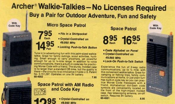
Instead, the new 1977 rules called for the move of these toy walkie-talkies to five specific frequencies in the 49 MHz band, 49.830, 49.845, 49.860, 49.875, and 49.890. Under the new rules, the toy 27 MHz walkie-talkies could not be sold after March 1978.
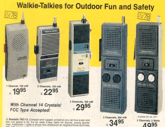
We can see the transition from the Radio Shack catalogs for 1978 and 1979. The 1978 issue showed these toy walkie-talkies for 27 Mhz:
The 1979 issue showed similar models, but for 49 MHz:
One bit of confusion is added by the fact that 100 mW walkie-talkies for 27 MHz remained on the market. For example, if we turn in the 1978 catalog to the “toy” section to the “CB” section, we see a number of CB walkie talkies, some of which are 100 mW.
Under the old rules, these 100 MW units had a dual status. They could be used under Part 15 without a license, since they fully complied with the 100 mW limitation. However, these radios were also “type accepted” under Part 95 of the rules, meaning that they could be legally used by licensed CB’ers. (These “real” CB walkie-talkies also typically had a superheterodyne receiver, meaning that they didn’t make the annoying “rushing” sound when no signal was present.) The CB rules at the time allowed CB’ers to communicate only with other CB stations. Therefore, it was technically illegal to communicate between a “real” CB and a toy 27 MHz walkie-talkie. (Unlike the prohibition on retransmitting baseball games, nobody ever told me that my attempts to do so were illegal. However, I doubt if there were many prosecutions for this particular offense.) In the case of a cheap toy walkie-talkie, this would have been true even if the toy was being used by a licensed CB’er, since the radio wasn’t type accepted for CB use. But because of their dual status, the three100 mW walkie-talkies shown here could have been legally used to communicate with a toy walkie-talkie (since the radio was under 100 mW) or by a licensed CB’er to communicate with another CB’er (since the radio was type accepted under Part 95).
The 100 mW walkie talkies continued to be sold by Radio Shack and other retailers. In practice, some of these were sold as high-end toy walkie-talkies for kids, since the type-accepted units were generally of much higher quality. But technically, after 1978, the use of the 100 mW 27 MHz radios required a CB license.
In 1983, the FCC ended the requirement for CB licenses, as reported in the April 28, 1983, issue of the New York Times. (Technically, CB is now “licensed by rule,” meaning basically that a license is required, but if you follow the rules, you are automatically granted a license by 47 C.F.R. §95.404.)
Therefore, it once again became legal (as long as the user obeyed the CB rules) for an unlicensed person to use the 27 MHz radios, whether they were the 100 mW model or one of the more powerful ones.
 Miss Peggy Stohl is featured on the cover of the 23 June 1923 issue of Radio World. The magazine reports that the roads are crowded with radio equipped vacationists, some of whom can’t wait until they arrive to listen in. Miss Stohl is in that category, as she listens to the radio while her garage man hurries along with some gas.
When she wasn’t listening to the radio, it appears that Miss Stohl was a chorus girl with the Zigfeld Follies and other shows, as shown by this entry at the Internet Broadway Database.
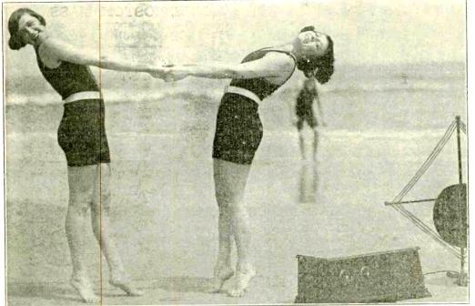 This image, from the cover of the July 19, 1924 issue of Radio World, shows Martha Breesh and Edna Jameson dancing on the beach at Atlantic City. According to the magazine, the two attractive vacationists are doing a Nymph-like dance on the beach, to the tune of a fox trot coming over the radio. Miss Breesh and Miss Jameson report that health and beauty depend on judicious exercise, and that they rate beach dancing to radio music as the apex of judiciousness.
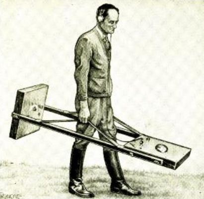 80 years ago, this was the latest in metal detectors. This unit, shown in the August 1934 issue of Radio Craft magazine, is similar in concept, but larger in size, to inexpensive metal detectors available today. It consisted of a one-tube oscillator along with a five-tube receiver. When the oscillator’s coil came in proximity to metallic objects, the frequency shifted, and the change in frequency could be determined from the receiver. The oscillator is mounted in one cabinet, with the receiver in the other.
The complete plans were in the magazine, which also reported that the unit could be purchased commercially. It was reported as being sufficiently sensitive to detect a piece of metal 16 inches square at a depth of 15 feet.
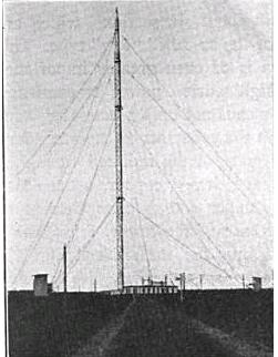
German station at Sayville, Long Island, allowed back on the air.
A hundred years ago today, August 21, 1914, President Wilson resolved the issue of use of wireless stations in U.S. territory by the warring nations. After protests from Germany, whose cable had been cut and had only wireless contact with Germany, it was decided that the warring nations would be permitted to send coded messages from their stations in the U.S.
Largely because of the practical impossibility, there would be no censorship of cable traffic on the remaining transatlantic cables.
As noted here earlier, it was Hiram Percy Maxim who brought to the government’s attention the German’s transmission of coded messages.
Among the newspapers carrying the report was the 22 August 1914 edition of the New York Tribune.
Read More at Amazon:
With the Great War, the wireless telegraph was clearly coming of age and was relied upon by the warring powers. The need for wartime communications was best illustrated by the Battle of New Orleans. The War of 1812 should have ended with the signing of the Treaty of Ghent on December 24, 1814, but word didn’t reach Louisiana in time to prevent the Battle of New Orleans from taking place on January 8, 1815.
By the time of the American Civil War, the telegraph had become an important tool of war, and both building and destroying telegraph lines became important military tasks.
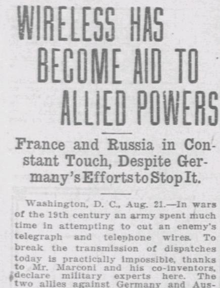
The Great War was the first in which cutting telegraph lines was no longer a strategic priority. This was recognized early in the war, as shown by this report in the El Paso Herald, Aug. 21, 1914:
WIRELESS HAS BECOME AID TO ALLIED POWERS
France and Russia in Constant Touch, Despite Germany’s Efforts to Stop It.
Washington, D. C, Aug. 21. In wars of the 19th century an army spent much time in attempting to cut an enemy’s telegraph and telephone wires. To break the transmission of dispatches today is practically impossible, thanks to Mr. Marconi and his co-inventors, declare military experts here. The two allies against Germany and Austro-Hungary, France and Russia, are probably in constant touch every hour indeed every minute, of the day and night.
The can talk right over Germany, Moscow and Paris can cooperate perfectly. Probably Gen. Joffre and grand duke Nicholaievitch know each of them what the other’s forces are doing from hour to hour.
An incident of the Balkan war shows the remarkable possibilities of wireless. The allies bottled up Adrianople. holding all roads to Constantinople. But in the city was a 1-1/2 k.w. Marconi wireless telegraph station of the portable type. At no time did the station fail, and in the course of the siege, more than 450,000 words were transmitted to headauarters without hitch.
lhe allies attempted to stifle the station by placing wireless outfits to the east and west of Adrianople, but their attempt to “jam” the Turkish signals was in vain.
Usefulness Is Demonstrated.
The usefulness of wireless was also shown in the recall of certain ships at the outbreak of the present war. One ship was brought back after she had proceeded within two days’ journey of Europe, and thus was saved from the enemy.
Many small craft have been seized, because they were at sea. at the outbreak of hostilities and had no wireless. The effect of this experience will undoubtedly be the cause of a wide use of air communications, as a kind of assurance against capture by a hostile warship.
Austria-Hungary has four important government wireless stations; Germany, 17. France, 18; Russia, 28; and Great Britain, 68.
Try To Insure Privacy.
Many means are now used for insuring the privacy of a wireless dispatch. The Marconi stations are designed to obtain this result by changing the wave length of the transmitter at frequent intervals.
This change can be made in a fraction of a second. The operator can shift his “tune” after every three or four words if he considers it necessary. Just before the shift he sends a code letter indicating to which wave length he is about to change. The operator at the station receiving makes the necessary readjustments to follow him without difficulty. It is believed that this system, properly carried out, is eavesdropper-proof.
Eiffel tower station, which France depends upon for communication with Russia, has the advantage that interference is practically impossible, owing to the peculiar sound of the signal emitted.
In other war news, the paper reported that Germany has lodged a protest with the U.S. State Department regarding the German wireless station in New Jersey. Cables between the United States and both France and England were still in operation, without American censorship. But since the German cable had been destroyed, the only method of communication between the United States and Germany was by wireless. The German charge d’affaires protested, and the matter was referred to President Wilson, who the paper noted might impose the same censorship on England and France.
Read More at Amazon
 This illustration is from the 1914 text “Wireless telegraphy: a handbook for the use of operators and students“.
It shows the somewhat cramped, but well equipped, wireless cabin of the Cunard Line’s R.M.S. Franconia. The wireless equipment was supplied by the Marconi Company, and consisted of a 1-1/2 kw spark transmitter, in addition to a totally independent 500 watt emergency transmitter. The receiver consisted of either a magnetic detector or a Fleming valve.

RMS Franconia
(Photo, Wikipedia.)
The first voyage of the Franconia was from Liverpool to New York in February, 1911. She served commercially until 1915, when she was called in for use as a troop transport in the Mediterrranean. She was sunk by a German U-Boat on October 4, 1916. Fortunately, she was carrying no troops at the time, but of the 314 crew, 12 were lost. The ship, along with the equipment shown above, lies at the bottom of the Mediterranean, 195 miles east of Malta.