In an earlier post, we looked at how the Defense Civil Preparedness Agency had been planning for emergency broadcast antennas in 1973. The agency and its predecessors had long recognized the need for dissemination of information by radio, and had commissioned a number of studies on the subject. One which took a comprehensive look at the subject was conducted by Technical Operations Incorporated of Burlington Massachusetts. The study culminated in a report issued on 7 January 1963, entitled “The Civil Defense Role of Radio Broadcasting in the Postattack Period.”
The report began by identifying three distinct phases of the postattack period. The first was the Buttoned-Up Period, during which time the population would be confined to shelter because of high radiation levels or because further attack was anticipated. This would be followed by the Emergence Period when some outside exposure would be possible. At such time as a full workday was possible outside of the shelter, the Recovery Period would begin and recovery would be the focus of the public’s activities. Each of these time periods had distinct requirements with respect to broadcasting, and the report then moved on to discuss the numerous broadcast needs.
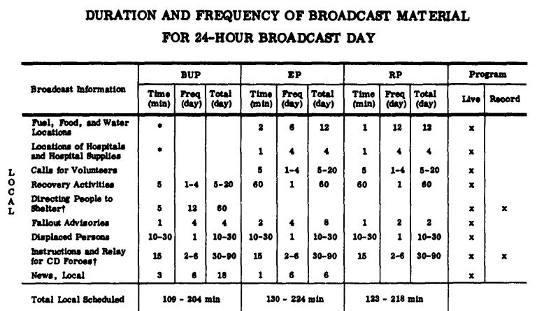
The first broadcast information discussed related to fallout, which would need to be broadcast frequently during the Buttoned-Up Period to facilitate planning by shelterees. In addition to general forecasts, these would include warnings of local hot spots, instructions on methods of decontamination and identification of safe foods, and information on the length of time over which shelter supplies would need to be rationed.
Broadcasts would also need to convey a large amount of information as to how the public could access emergency services, and would also serve a role in alerting those furnishing those services. Locations of food and water supplies could be broadcast, along with admonitions to avoid hoarding of those limited supplies. Locations of emergency hospitals and medical supplies could be broadcast, along with pleas for blood donors and volunteers to staff the hospitals. Information as to sources of fuel and power could be broadcast. And if the electrical mains were operative, the instructions might include rationing instructions. If fires were burning out of control, the broadcasts might include calls for volunteers to assist in their control, as well as warnings of fires close to particular shelters.
Much educational programming would be necessary. In addition to broadcasts of food decontamination methods, emergency first aid instructions would need to be broadcast during the Buttoned-Up Period, since no outside medical aid would be available at that time. Since some shelters might be stocked with radiological instruments with no trained personnel, this training could be broadcast as well, along with training on sanitation, shelter management, rationing of supplies, and even disposal of the dead.
During the Recovery Period, a very high civil defense priority would be re-establishment of public transportation. Once again, broadcasting would play an important role, since it could be used to call drivers back to work, as well as to announce schedules.
Even apart from this vital information, radio would be important to the public morale. The report stressed the importance of morale-boosting messages from the President, as well as by state and local leaders. Similarly, to stop the spread of rumors and boost morale, it was deemed important to broadcast news of the attack and counterattack. This would also prepare the people for the conditions they would face upon emergence, and also instill a feeling in the people that this was not a personal disaster, but that the whole population of the nation was included. The report noted that good news is always best, but that even bad news is superior to no news at all, since it helps define the environment and diminish uncertainty. The report noted that any unaffected regions of the country should be kept up to date, in order to properly tailor relief and rescue operations.
Broadcasts should frequently give the time and date, since in such emergencies, people frequently lose track. In addition, program schedules should be announced, in order to facilitate conservation of scarce batteries.
Broadcasting could also play a role to re-establish normal commerce during the Recovery Period. Even during the Buttoned-Up Period, the report recommends that people be informed as to the rules and regulations over such things as “whether the needy will be allowed to take what they require without being charged with illegal looting.”
Radio would also play a role in the care of displaced persons, since stations could broadcast information to reunite families who were separated at the time of the attack. These broadcasts would include locations of camps, shelters, and displaced person centers. In addition, during the nighttime hours, lists of people safe in various shelters could be broadcast for the benefit of their families in other areas.
Evacuation instructions and warnings of another attack would obviously have a high priority for broadcast.
The report notes that broadcast stations would undoubtedly be used to call civil defense personnel and members of the National Guard to duty and provide some instructions. Broadcast stations could even be used to relay civil defense messages from one area to another. The nighttime hours, in particular, might be put to use relaying such official messages, and civil defense officials in other areas could be assigned to monitor broadcasts from neighboring areas.
Finally, the report recommends that some entertainment should be furnished, particularly during the time in which people are in shelters. It notes that “music properly chosen many substantially aid morale in the rebuilding phase.” The report warned, however, that people with battery-operated radios should be advised to conserve batteries by listening to only a minimum amount of non-essential programming.
The overall contents of the broadcast day of a typical local station are shown in this chart:
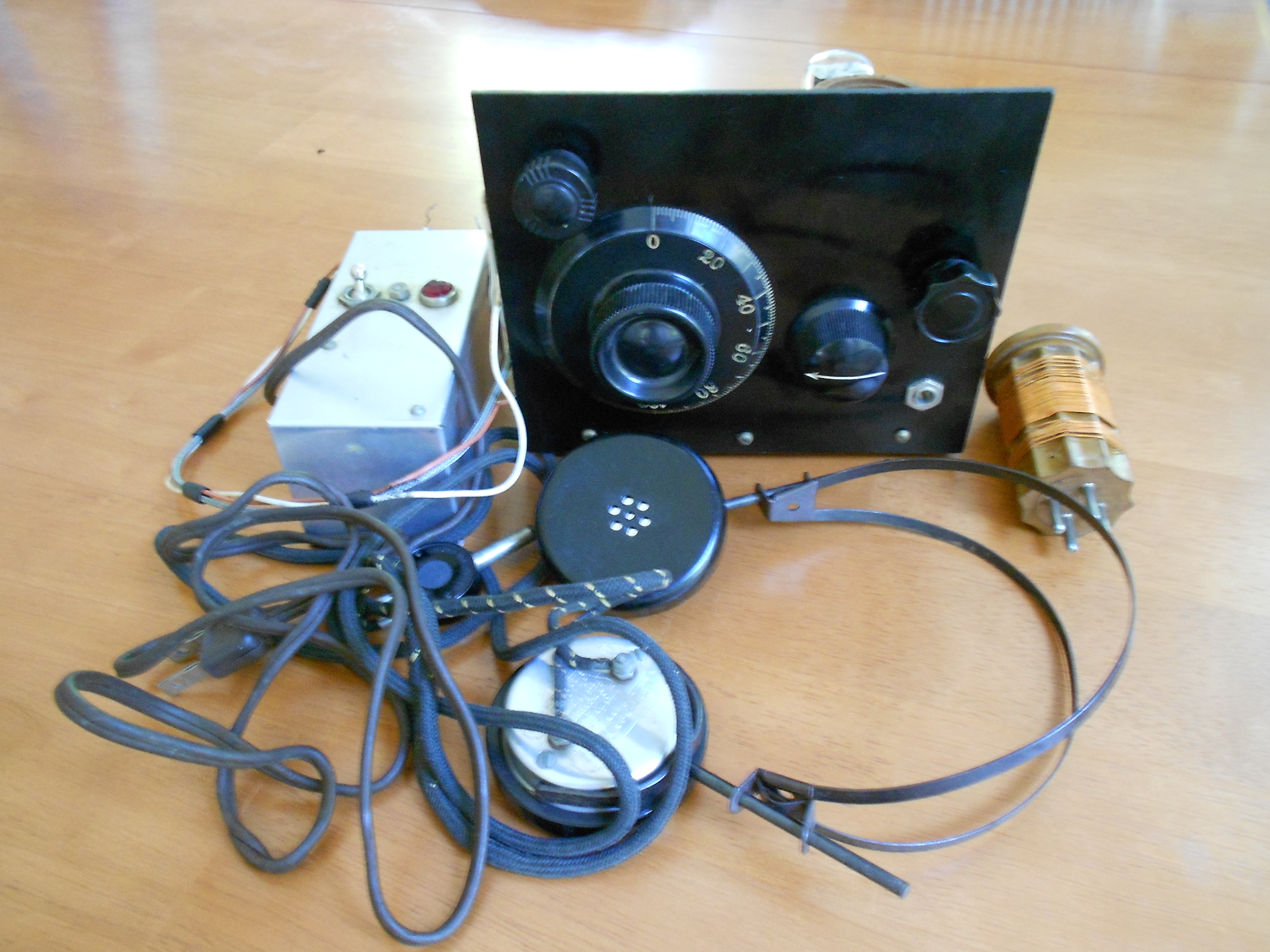
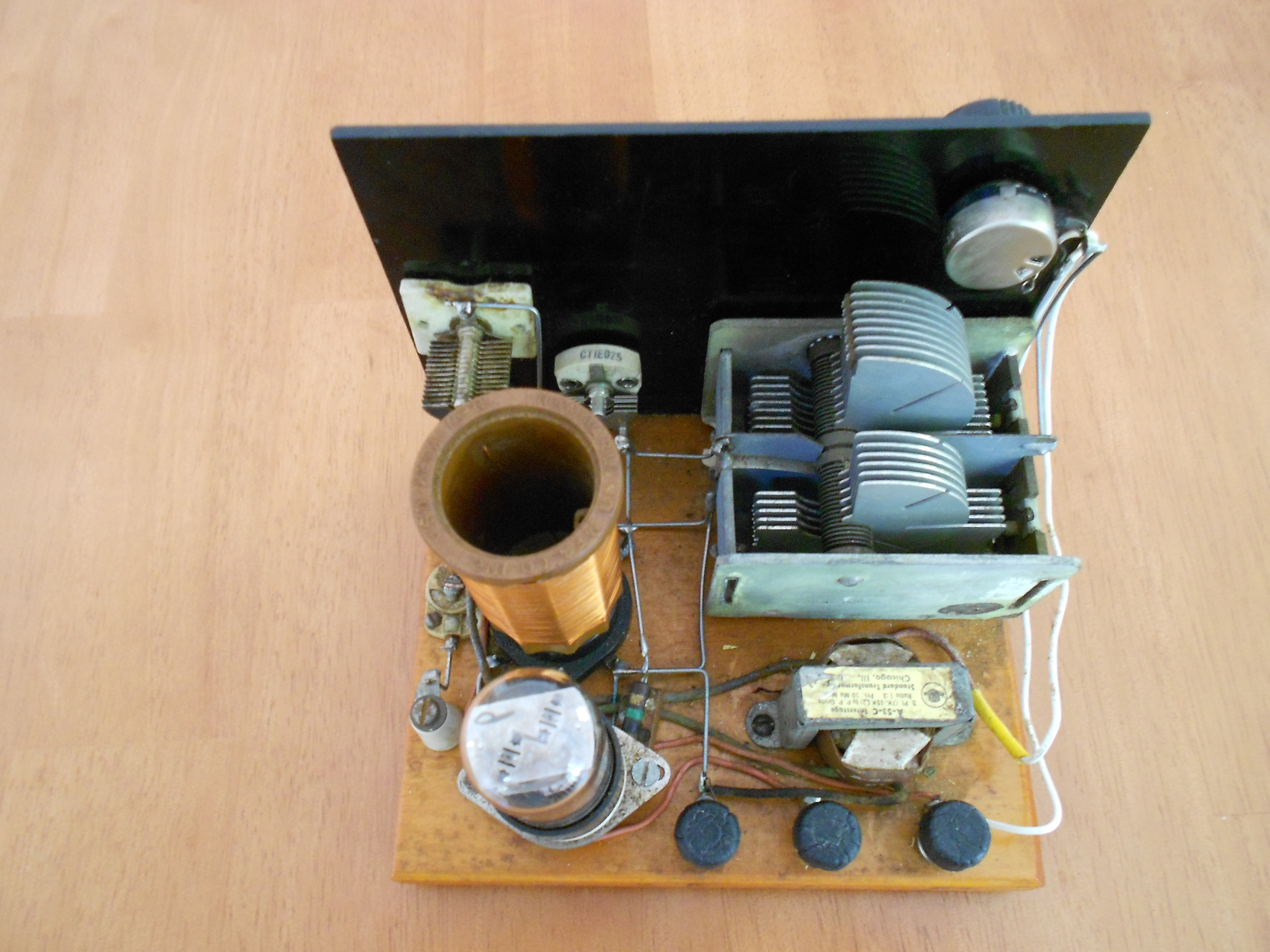
After identifying all of these needs, the report goes on to a discussion of how these needs can be satisfied. While some other options (such as public address systems) are briefly discussed, the only reasonable method of addressing these needs was with standard AM broadcasts. Virtually all American households had a radio receiver, and a large number had a battery-operated set. The report even notes that “for the really economy-minded, there are crystal sets selling for as little as $1.49,” which would be suitable for receiving local stations with no batteries, but with adequate antenna and ground. The footnote for this assertion is to the Radio Shack catalog, and the price obviously refers to the “Rocket Radio” shown at the top in the illustration at the top of this post.
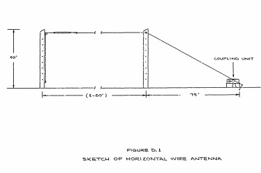
The report did address many of the practical issues confronting broadcasting in the post-attack environment. Presumably, most information would originate at the civil defense Emergency Operations Center (EOC), and links would be necessary to studios or, preferrably, direct to the transmitter site. Since telephone lines would be vulnerable, mobile broadcast units would be advisable, although the report toyed with the idea of installing AM transmitters directly at the EOC, or the use of mobile or even airborne transmitters. Protection of station staff and equipment was addressed in this and other studies.
The report lamented the fact that the radio industry, even though some personnel served on relevant civil defense committees, largely lacked civil defense plans. For example, even radio station switchboards were poorly suited for civil defense needs. As addressed in my earlier post, vulnerability of transmitter towers to blast damage was a very big issue, as was fallout sheltering for station staff.
Station power was discussed, although the report noted that some stations already had emergency generator capability.
At the time of this report, public shelters were not stockpiled with radio receivers, and the report noted that this oversight should be rectified. This, of course, was never done, apparently the planners going along with the reasoning, “surely some people will bring radios to the shelter.”