Category Archives: Radio history

1954 High Gain Low Drain Portable

RadioElectronics1954March

The plans for this “high gain, low drain portable radio” appeared in the March 1954 issue of Radio Electronics magazine.  It appears to be a good performer, but it was designed both for performance and low battery drain, and the author explained why:

When anybody anybody mentions “portable radio,” most of us think immediately of the entertainment it can provide.  The Set can go with us on picnics, vacation trips, and boat rides. We can enjoy ball games, national events and all our favorite programs while we work, play, and travel. But there is a serious side to this matter. In these days of H-bombs and supersonic jets, a portable radio might mean the difference between life and death. If that terrible day should ever come when air-raid sirens wail for real, the Conelrad system will go into effect. If worst comes to worst, if power goes out and wires down, civil defense messages and other essential communications will continue. In such an emergency, a portable radio can become a very important item.

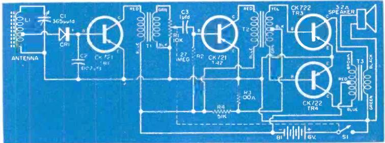
With that in mind, the key design factor was low battery drain. A few years later, transistors would make that goal easy. But the current transistors on the market, while suitable for low-powered audio, weren’t yet ready for use with RF. Therefore, the design of this set was a hybrid–it contained two tubes, a 1E8 serving as oscillator and mixer, with a 1AD5 serving as IF amplifier. Then, solid state took over, with a 1N34 diode as the detector, and two CK722 transistors providing enough audio amplification to drive a speaker. For more distant stations, a headphone jack was provided.

Because of the hybrid design, the set required three batteries, but they were all set up to minimize current draw. The transistors were powered by 4.5 volts, provided by three dry cells. The filaments were powered by another 1.5 volt dry cell, but the author noted that these could be run on a battery so low that it was no longer useful for a flashlight. In addition, there was a potentiometer in series with the filaments. This would serve, to a certain extent, as a volume control. But more importantly, it would allow the filament current to be set to the lowest possible position.

The B+ for the tubes was provided by a 45 volt battery. Here, another battery saving trick was employed. The set contained a switch for local/long-distance. For strong local stations, a 56k resistor was switched in series with the B battery. This reduced the B+ current to only 50 microamps, just barely enough to keep the RF section running. For more distant stations, this resistor was bypassed, and the tubes ran on the full 45 volts, drawing about 1.6 mA.

The author reported that the set worked well with local stations, even in a skyscraper, or even in a subway or tunnel. He reported pulling in stations as far as 500 miles away with the telescoping antenna, normally designed for use as an automobile antenna.

RadioElectronics1954MarchSchematic

Click Here For Today’s Ripley’s Believe It Or Not Cartoon


Chiyono “Suzy” Cugita Suzuki, J1DN, J2IX

1936AprRadioNews

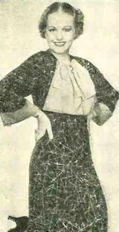
Shown here in the April 1936 issue of Radio News is Miss Chiyono “Suzy” Cugita, then J1DN, and later, after her marriage and 1937 move to Tokyo, Chiyono Suzuki, J2IX. Five years before Pearl Harbor, she was doing her best to promote international good will on the ham bands. She was active on both phone and CW, and served as the foreign QSL manager for JARL.

The magazine notes that she was Japan’s only YL operator, and had contacted more than a hundred U.S. hams, as well as Australia, South America, and Siberia.

Her QSL and more photos can be found at HamGallery.com.

Click Here For Today’s Ripley’s Believe It Or Not Cartoon



Ansley Paneltone Built-In Shortwave Receiver

1946AprilPM

In 1946, the war was over, and it was time to start designing the dream house.  A dream house wouldn’t be complete without a built-in radio.  And if you’re going to build a radio into your house, it may as well be a shortwave radio!

Shown here in the April 1946 issue of Popular Mechanics is just that.  It is the Ansley Paneltone receiver.  With one of these babies, you would have a 17 tube radio behind the wall. In addition to the standard broadcast band,it would cover both FM and shortwave, with pushbutton tuning. There was also provision for a phonograph connection. The 12 inch speaker would put out 15 watts of room filling audio.

I haven’t been able to find any evidence that this set ever made it into production. I have found references to the smaller 7 tube set shown in the same article, which covered just the standard broadcast band. It too featured pushbutton tuning, and its six inch speaker put out five watts.  You can find more information about that set, which also carried the Ansley Paneltone name, at RadioMuseum.org.


Click Here For Today’s Ripley’s Believe It Or Not Cartoon


1941 Motorola Bike Radio

1941Apr27RadioGuideThis ad appeared 75 years ago today in Radio Guide magazine, April 26, 1941.  I suspect a lot of boys drooled over the prospect of having a radio on their bike.  For details on how to “win” one “free,” they were to write to the Boy Sales Manager of the magazine.  Undoubtedly, they would be told how many subscriptions they would need to sell to win the radio.  I suspect they would have to sell quite a few.  The magazine had a single issue price of ten cents, and an annual subscription was $4.  The radio itself appears to be the Motorola model B-150, with a retail price of $19.95.

The radio was probably a fairly good performer, being a three-tube superhet. Its tube lineup consisted of a 1A7GT, 3A8GT, and 1Q5GT, and had a 4 inch speaker. More information is available at RadioMuseum.org.

The set was powered by a combination A-B battery from Ray-O-Vac, which mounted on the frame of the bicycle. It also featured a whip antenna.  One novel feature of the set is that it had permeability tuning, meaning that the tuning knob adjusted the slug of an inductor, rather than moving a variable capacitor.

You can see a surviving example of the set at OldBike.eu.  Update:  Greg Farmer sent a link to a nice example of the radio at this link.  The radio, along with a bike of the same vintage, was on display at the Pavek Museum of Broadcasting in St. Louis Park, MN.

Click Here For Today’s Ripley’s Believe It Or Not Cartoon


1966 FCC HELP Proposal

1966HeathCB

Fifty years ago, the FCC was considering a new radio service which never came to fruition. This was the Highway Emergency Locating Plan Radio Service (HELP), which was petitioned for by the Automobile Manufacturers Association, Inc. Described in the June 1965 issue of Popular Electronics, the plan called for two channels within the existing CB band, 27.235 and 27.245. For those familiar with 23 channel CB radios of the day, these were the mysterious channels 22A and 22B, which were included on the dial, but disabled.

HELP would be a new radio service, but would allow existing Class D CB operators to operate on thos channels for motorist assistance. The idea was the vehicles would be equipped with radios for these channels, for use in summoning help in an emergency. Land stations would be allowed 30 watts, with mobiles using 5 watts.

A March 1966 FCC order looked favorably on the proposal, and FCC staff was tasked with researching it further. However, it never came to fruition.

1966AvcommManufacturers were apparently eager to get on board with the HELP service. As mentioned above, most 23 channel CB radios included channels 22A and 22B. In the 1965 ad shown above, Heath advertises this 25 channel CB transceiver, including the 2 HELP channels. An asterisk next to the description of those channels points out that the FCC petition is still pending.

And shown here in the April 1966 issue of Radio TV Experimenter is a 200 milliwatt handheld, the Mark 1 HELP Transciver from the Avcomm Division of what the magazine calls “a company with the unlikely name of Ajax Floor Products Corp.”  The crystal controlled radio would operate on any frequency between 25-50 MHz.  The company promised coverage of up to a mile in tall buildings or heavy traffic areas, up to five miles line of sight, and 7 miles in open country or over water.  The receiver was a superhet, and the magazine opined that it looked “like a good bet to toss in the glove compartment if you want the reassurance of having a rig along with you on a trip without having to make a permanent installation.”

An interesting discussion of the HELP proposal can be found at RadioReference.com.


Click Here For Today’s Ripley’s Believe It Or Not Cartoon


1941 Popular Mechanics One Tube Receiver

1941AprilPM

Seventy-five years ago, this month’s issue of Popular Mechanics,
April 1941, carried the plans for this simple one-tube receiver, which covered the broadcast band, as well as the 160 and 80 meter bands.

Using a 1S4 Tube, the set required a B battery of only 6 volts, meaning that it could be run with four flashlight batteries in series. Another two flashlight batteries in parallel powered the filaments, and the total cost of batteries was only 30 cents.

Also presented was an audio amplifier on a separate chassis, also using a 1S4, which would drive a three inch speaker. Or, as the user in this drawing is shown, the set could be run by itself with headphones. Volume and regeneration were controlled by an adjustable tickler coil, keep the parts count of the set low.

1941AprilPMSchematic

Click Here For Today’s Ripley’s Believe It Or Not Cartoon


1941 Compact Portable Transmitter

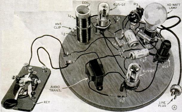
1941AprilQSTSeventy-five years ago this month, the April 1941 issue of QST carried the plans for this simple one-tube CW transmitter for 80 and 40 meters.

The set was billed as a compact portable transmitter for field or emergency use, but could also function as the control stage of the home station until being put into place for field duty. According to the article, the total cost, including tube and cabinet, was less than $12.

The set required 6 volts for the filament, and 250 volts DC for the B+. This could be derived from batteries, and the article pointed out that this would be good for several hundred hours of intermittent operation. But it was really designed to run from the vibrator power supply of the car radio. The article advised builders to consult with the manufacturer of the car radio to get the wiring diagram, since those could vary considerably. But the car radio’s power supply would be expected to have a typical output of 200-250 volts at 50 mA. A single pole double throw switch could be added to the car radio to switch the power from the transmitter to the receiver.

The top of the set had three insulators. Two had connections that would be used with a doublet, and the third was to be used with a single wire antenna. The article noted that the transmitter could tune virtually any antenna.

1941AprilQST2

Click Here For Today’s Ripley’s Believe It Or Not Cartoon


1926 Carborundum Crystal Set

1926AprilRadioHome

Ninety years ago, the April 1926 issue of Radio In The Home magazine carried the plans for the “200 Mile” crystal set shown below.  The author describes the set in the following terms:

Many readers will be surprised to learn that a simple crystal set has given a fairly consistent nightly range of more than 200 miles. Yet this is not unusual; it is just the average performance of a well designed crystal set and has been done repeatedly this and the latter part of last winter.

From our location in Niagara Falls, New York, with an aerial and location no better than the usual, we have regularly listened to Pittsburgh, 200 miles, to Schenectady, 250 miles and to Chicago, 450 miles.

This record may seem out of the ordinary and indeed we ourselves were surprised at first. But the manner in which the first set and others of the same type, used on our own and other people’s aerials operate, has convinced us that the feat may be duplicated almost at will.

It then goes on to describe the set, emphasizing how low-loss components are used throughout.  Any detector could be used, but for best results, “it should also bear a certain relation (rather difficult of exact specification) to the input impedance. These conditions can best be met through use of the electrically controlled carborundum permanent detector (Carborundum Stabilizing Detector Unit).”

The Carborundum Stabilizing Detector Unit was manufactured by the country’s only producer of carborundum (silicon carbide), the Carborundum Company, which just happened to be also located in Niagara Falls, New York.

The carborundum detector does have the advantage of being permanently fixed, with no cat’s whisker to fiddle with.  It requires a reverse bias, provided by a flashlight battery.  The Carborundum Stabilizing Detector Unit included a potentiometer for adjusting the bias voltage.  So the listener accustomed to fiddling with the cat’s whisker could instead fiddle with the potentiometer.

1926AprilRadioHome2


Click Here For Today’s Ripley’s Believe It Or Not Cartoon


1941 National HRO FM Receiver

1941AprilNationalFM

Here’s what the well equipped audiophile would have in his living room 75 years ago. The receiver is unmistakably made by National, and it’s shown in the April 1941 issue of FM magazine.

The ad’s caption conceded that the set was designed primarily as a communication receiver, but that it gave superb FM rception.  It had dual high fidelity output circuits, an excellent signal to noise ratio, and extreme sensitivity.  The ad doesn’t say so, but it would look nice in any living room.

Unfortunately, I haven’t been able to identify the model number, or even whether this receiver actually made its way into production.  According to the ad, the set was described in the December 1940 issue of the magazine, but that issue isn’t available online.

Click Here For Today’s Ripley’s Believe It Or Not Cartoon


Kalaupapa Leper Settlement/National Historical Park, Hawaii

Kalaupapa National Historical Park. NPS photo.

Kalaupapa National Historical Park. NPS photo.

During the ARRL National Parks On The Air (NPOTA) event, Amateur Radio operators are setting up their stations in various units of the National Park Service and making contact with other Amateurs around the world. Since the beginning of the year, there have been over 3600 activations from 378 different parks, with over a quarter of a million individual contacts.

One interesting aspect of this event is learning about the different parks, some of which I did not even know existed. One of the most fascinating is Kalaupapa National Historical Park in Hawaii, located on an isolated peninsula of the island of Molokai.

The peninsula was originally the Kalaupapa Leper Settlement, created in 1866 to isolate Hawaiians suffering from Hasnen’s disease, commonly known as leprosy. From 1866 to 1969, a total of 8500 persons were relocated there for the rest of their lives. Since the 1940’s, Hansen’s disease has been curable with antibiotics, and it was also learned that the disease was not nearly as infectious as imagined. The settlement closed in 1969, but residents, many of whom were disfigured by the disease, were allowed to remain there for the rest of their lives.

Father Damien, photograph by William Brigham.jpg

Father Damien shortly before his death. Wikipedia photo.

For many years, the residents were cared for by Belgian missionaries from the Congregation of the Sacred Hearts of Jesus and Mary. The most well known was Father Damien, who served there from 1873 to 1889, when he himself died of leprosy. He was canonized by the Catholic Church in 2009. He was joined in 1883 by nuns including Mother Marianne Cope, who served there until her death in 1918. In 2012, she was also canonized by the Catholic Church.

When he arrived, Father Damien was instructed by his superiors not to touch his flock, and to eat only meals that he himself had prepared. Finding it impossible to minister under these conditions, he eventually ceased following these directives. After he had been there about fifteen years, he was cooking and spilled some boiling water on his foot but felt no pain. He purposely poured boiling water on his foot, but felt nothing, because he himself had leprosy.

He would normally begin worship with the words, “my fellow believers.” But that Sunday, he began “my fellow lepers.”

The historical park was established in 1980 to preserve the physical settings, which is still home to a few elderly surviving patients. The park also constitutes Kalawao County, Hawaii, the second least populous county in the United States, with a 2010 population of 90. (after Loving County, Texas, with a 2010 population of 82).

Access to the park is extremely limited, requiring an advance permit. Access by sea is prohibited. The park is serviced by Kalaupapa airport. The only land access is by a 3.5 mile mule trail connecting the penninsula to the rest of the island atop a 1600 foot cliff.

KH6BWG Silent Key notice, June 1959 QST.

KH6BWG Silent Key notice, June 1959 QST.

The Amateur Station at the park was KH6BWG, the William O Kupele Memorial Club Station, which bears the call sign of the settlement’s last resident ham, William O Kupele, who died in 1959. Because of the park’s isolated location, Amateur Radio plays an important role in emergency communication. The main purpose of the KH6BWG team’s visit was to administer license exams to residents, and to ensure that the settlement’s station was in good operating condition. The settlement is connected to the outside world not only by HF, but also by VHF, since the team ensured that contact can be made with Hawaiian repeaters. A special concern was ensuring that the settlement’s emergency evacuation location had VHF access with the outside world.  The park is in the process of formulating a management plan for preserving the site, and recognizing the communications challenges, the plan includes the use of Amateur Radio as one of the park’s vital links.

As a secondary goal of the trip, the KH6BWG group made about 2000 NPOTA contacts with other hams, including one with me.

Read More At Amazon

For Young Readers

Click Here For Today’s Ripley’s Believe It Or Not Cartoon