Category Archives: Radio history

1936 Two Tube AC-DC Regen

1936novradiocraft

The plans for this simple two-tube set appeared eighty years ago this month in Radio Craft magazine, November, 1936.

With plug-in coils, the set tuned 10 to 600 meters, and the author reported picking up numerous European and other foreign stations in New York City with excellent volume. The set employed two tubes, either type 37 or 76. One served as rectifier, with the grid and plate terminals tied together. The other served as the regenerative detector which was “capable of picking up even the faintest of signals.” An antenna of 30-100 feet was recommended. No ground connection was necessary, since the house current took care of the ground.

1936novradiocraft2


1956 Boys’ Life Radio Contest

1956octbl1

Sixty years ago this month, the Boys’ Life Radio contest was once again underway, and radio made the cover of the November 1956 issue of Boys’ Life, depicting a ham who took a break from his duties in the school Thanksgiving  play to work some DX.

This cover was the work of frequent Boys’ Life artist Harold Eldridge. According to the magazine’s description:

Miles Standish thought he had it touch, having to defend the pilgrims with just a handful of soldiers armed with blunderbusses. But pity the poor dramatics coach who has his Indians better trained than his hams. That friendly Algonkian in the window probably pictures the coach back in the high school auditorium, sweaty hands clutching the curtain ropes, but not John Alden, no Priscilla Mullen, and no Miles Standish yet appearing in the wings.

According to the magazine, the artist never did tell whether the DX’ing ham ever got back in time to cut some turkey on stage.


1941 One Tube Broadcast Receiver

1941novps

The duo shown here are putting together the one-tube receiver described in the November 1941 issue of Popular Mechanics.

1941novpmschematicThe set was billed as being for the beginner who wanted to graduate from the crystal set stage, or for the radio experimenter who enjoyed pulling in some DX, an ability this set possessed.  The single tube was a 117N7-GT, so it required no A battery.  Instead, the filament was powered by the AC line.  The set was so efficient that it would run on a 30 cent 4.5 volt battery supplying the B+ voltage.  The required parts, including the tube and battery, but not including the headphones, priced out at about $4.50, even accounting for recent price increases.


1916 One Mile Transmitter

1916octoberps

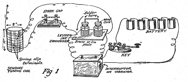
A hundred years ago, the October 1916 issue of Popular Science gave detailed instructions for constructing a transmitter capable of sending one mile, the diagram of which is shown above. The set was powered by nine volts, consisting of twelve dry cells wired in series-parallel.

When the modern reader looks at a diagram such as this one, it’s not readily apparent how the set could actually work, since one critical part of the transmitting coil is not shown. The article noted that plans for constructing the coil were available in many books, but recommended that it was simpler and cheaper to simply buy one. It suggested an automotive spark coil, which could be obtained from a garage or electrician at nominal price. The article noted that even a new coil would cost no more than three or four dollars.

Such a coil is actually a transformer, and the primary is wired at the factory in series with an normally-closed interrupter. When the coil is energized by the nine volts, it creates a magnetic field, which opens the interrupter contact. This breaks the circuit, and the coil de-energizes, which results in the interrupter closing again, allowing the process to repeat. The net result is that an interrupted direct current is produced in the primary, and this induces an alternating current in the secondary. The secondary is a large enough voltage to make a one-inch spark in the attached spark gap.

1916octoberpssparkgapThe spark gap, shown here, is constructed from two pieces of zinc mounted on a hardwood base boiled in paraffin.  The key could be an ordinary telegraph key, which sold for about 75 cents, or could be homemade.

1916octoberpsloadingcoilThe article stressed that the loading coil, shown here, was required to keep the transmitter on the correct wavelength, below 200 meters, to comply with federal law.  It was constructed between two square boards, about 12 by 12 inches.  FInally, an aerial of no more than 75 feet was required, and the article contained pointers for its installation as well.

Finally, the article described operation of the set:

Whenever the key is pressed, if the set is properly connected and adjusted, a bright, snappy, singing spark will jump across the gap. Each spark starts a train of high frequency currents oscillating back and forth in the aerial wires, and a train of electromagnetic waves is radiated into space. A suitable wireless receiver located where a portion of these radiated waves will reach it, will pick up some of their energy and produce from it a sound which indicates the dot-and-dash buzzes of a Morse signal.


WW2 CBS Broadcasts

One of the fascinating parts of collecting old radios is pondering the kinds of programs they pulled in over the years.  Chances are, the radio was used to listen to countless hours of news, music, entertainment, and sports.  They were a witness to history, but the frustration is that we can no longer listen to the programs that were broadcast.  Programs generally weren’t recorded, and most of the live programs that were broadcast were lost.

Fortunately, there are exceptions, although most of them were the result of accidental preservation.  One example is documented in this news story from KIRO in Seattle:

KIRO Radio accidentally saves American history

Even though it was contrary to network policy, KIRO made a practice of recording CBS network news on 16 inch discs, so that they could be replayed at a more convenient hour for West Coast listeners.  Fortunately, someone rescued these discs when they were to be discarded, and they are now in the collection of the University of Washington.  They are gradually being digitized, and many are available at this link.  The first one in that collection, for example, is a broadcast from September 1, 1939, and include a report from London of the declaration of war.


1946 80 Meter Transmitter from Popular Science

1946octps

Seventy years ago, the October 1946 issue of Popular Science showed the beginning ham how to put together this compact transmitter for 80 meters (on the left in this photo).

The set employed a single 7N7 dual triode, and was said to be capable of real performance. But the article warned to bear in mind that “the 80-meter band is crowded with high-power outfits, so you’ll have the best chance of getting through during the relatively quiet hours.”

The set was mounted on a 5×7 wooden base, and required a 250-300 volt power supply, as well as filament voltage. The antenna tuning unit was mounted on a separate chassis, with twisted lamp cord connecting the transmitter and tuner.

1946octpsschematic


NBC Shortwave Listening Station, Bellmore, Long Island, 1941

1941oct25radioguide

Shown here in the October 25, 1941, issue of Radio Guide is the Shortwave Listening Station which the NBC network had recently installed at Bellmore, Long Island. The station was in operation 24 hours a day, and the staff of 24 foreign language experts and radio engineers kept tab on the war of words coming from Europe.

The issue also reported on a publicity stunt recently conducted by Berlin Radio. For a number of days, the station had announced that Lord Haw Haw had been banned from the air. Then, an announcement followed that Lord Haw Haw would be allowed to come on the air and give his side of the story.

Many American editors fell for it, and the broadcast received plenty of advance publicity. However, Lord Haw Haw hadn’t been banned from the German airwaves. It was a publicity stunt in which he announced merely that the American networks refused to carry his propaganda.


1926 Homemade Battery Charger


1926octoberpmOne of the electronic components we take for granted today is the semiconductor diode for use as a rectifier. But even ninety years ago, if you wanted to build your own battery charger, you could do it at home, as shown by these plans from the October 1926 issue of Popular Mechanics.

To charge a six volt battery, this charger used a 12 volt doorbell transformer.  The rectifier consisted of a glass jar containing a solution of borax, with electrodes made of lead and aluminum.  The total cost of all of the parts was said to be $2.50.


Women in Radio: 1916

A hundred years ago this month, the October 1916 issue of Electrical Experimenter devoted a large portion of the magazine to “the Wireless Girl,” and featured on the cover this painting by George Wall.  Loyal readers will recognize the painting as being based on a photograph of Kathleen Parkin, 6SO/6BP, of San Rafael, California.  As we related in an earlier post, she built the quarter kilowatt transmitter shown here, along with a vacuum tube receiver, and had one of the more impressive stations on the West Coast.

In the Electrical Experimenter article, Miss Parkin writes of her interest in wireless:

With reference to my ideas about the wireless profession as a vocation or worthwhile hobby for women, I think wireless telegraphy is a most fascinating study, and one which could very easily be taken up by girls, as it is a great deal more interesting than the telephone and telegraph work, in which so many girls are now
employed. I am only fifteen, and I learned the code several years ago, by practising a few minutes each day on a buzzer. I studied a good deal and I found it quite easy to obtain my first grade commercial government license, last April.

It seems to me that every one should at least know the code, as cases might easily arise of a ship in distress, where the operators might be incapacitated, and a knowledge of the code might be the means of saving the ship and the lives of the passengers. But
the interest in wireless does not end in the knowledge of the code.

You can gradually learn to make all your own instruments, as I have done with my 1/4 kilowatt set.

There is always more ahead of you, as wireless telegraphy is still in its infancy.

Graynella Packer operating the wireless aboard the

Graynella Packer operating the wireless aboard the Mohawk.

Miss Parkin was not the only young woman at the forefront of radio, as the article cited a number of others. For example, Graynella Packer of Jacksonville, Florida, was the first woman wireless operator to serve on a commercial vessel, aboard the Mohawk of the Clyde Line, where she was in full charge of the vessel’s wireless.

Numerous other women radio operators were featured in the article, which stressed the role that wireless played in national preparedness.  The photo below shows a group of young women studying wireless at a summer preparedness camp.

1916preparednesscamp


1936 Radio Show

1936octradiocraft

This cover spread from the October 1936 issue of Radio Craft showed some of the new sets getting ready to hit the market for 1937, as seen at the September 1936 New York Radio Show. Some of the sets featured here include:

  • RCA Model 10-T
  • General Household Utilities Co. Model 1541 Teledial Console
  • United Motors Service Model 3209, a 32 volt farm set
  • General Electric Model E-155
  • Crosley Model 167 Console
  • Noblitt-Sparks Industries Rhythm King Model 1127
  • Philco Model 116X DeLuxe
  • Zenith Model 7D-148
  • Admiral Model AM 387
  • Stromberg-Carlson Model 145-L
  • Detrola Model 102-C
  • Emerson Model L-143