Category Archives: Radio history

Answer to Yesterday’s Puzzle

1968AprRadioTVExp

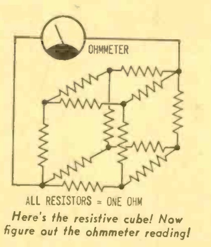
Yesterday, we showed this puzzle from the April-May 1968 issue of Radio TV Experimenter magazine. The question was simple enough–you had to figure out the net resistance between two opposite corners.

1968JunRadioTVExpFifty years ago, hobbyists encountering this problem probably started out the way I did, by scribbling the diagram on a piece of paper, trying to flatten it out, and then realizing that the standard equations for series and parallel resistors weren’t really of much help, since they were all hopelessly interlinked.

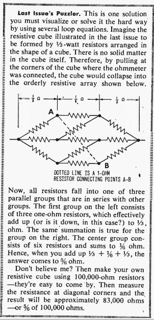
Fifty years ago, the reader had to wait two months for the answer, as shown here in the June-July issue. So I suspect that more than a few got twelve identical resistors, made them into a cube, and then measured.

I didn’t have to do that, because today we have that Google thingie, and I found this solution to the problem, as well as the video shown below, which takes a slightly different approach.

The key to solving this is to notice that the voltage reading at all three of the points marked “A” is the same.  And the voltage reading at all three of the points marked “B” is the same.  This is because the diagram is symmetrical, and a current flowing from the left to any of the points A is going to pass through an identical resistance.  And a current flowing from the right is going to pass through an identical resistor to get to any of the points B.

Since the voltage reading is the same, we can go ahead and make a direct connection between all of the A points, and another direct connection between all of the B points.  Since the voltages are the same, no current will flow, and there will be no effect on the circuit.

The effect that it will have, however, is making the problem a lot easier to solve.  At this point, we have three resistors on the left, all in parallel.  We have six resistors in the middle, all in parallel.  And we have three resistors at the right, all in parallel.  It’s easy to compute that the equivalent resistances are 1/3, 1/6, and 1/3 ohm.  And those values are in series; so we just add them up, and the answer is 5/6 ohms.

This video takes a slightly different approach to arrive at the same answer:


Resistance Cube Puzzle

1968AprRadioTVExp

Today we offer a deceptively simple looking puzzle, taken from the April-May 1968 issue of Radio TV Experimenter magazine.

The question is simple. This cube is made up of 1 ohm resistors on each edge. What’s the net resistance between two opposite corners? The answer will appear here tomorrow.


Selling Radios in 1938

Screen Shot 2018-04-02 at 2.03.33 PMThe man sneaking through the window isn’t a burglar. It’s a radio salesman trying to get a radio inside the house, where it can sell itself! The illustration appeared in the April 1938 issue of Radio Retailing in an article explaining how to sell.

The article explained that your canvassers can’t sell radios at the door, and they can’t get inside the door, because the homeowner is well aware that they’re just trying to sell.  And even if they do get inside, they’re not going to sell any radios armed with photos.

So to sell radios, the canvasser needs to stop trying to sell radios.  Instead, they needed to figure out a way to get a radio inside the house, where it could sell itself:  “The answer is to GET THE RADIO IN THE HOUSE.  And when I say get the radio in the house, I mean get the radio in the house by any lawful means at your disposal.  By trickery, by cunning, by anything under the sun but a hint that you want the lady to buy it.  By misrepresentation, if you will, provided you stick to your original story, even when you go back to sell.”

The article even advised having the boss go back to close the sale, rather than having the original salesman.  After all, the original salesman will go to great lengths to stick to his story that he’s not trying to sell anything.  The boss, on the other hand, has a bit greater aura of importance, and can probably close the sale.

The article speculated that if the original salesman handles both ends of the transaction, then he’ll probably place 100 radios and sell 80 of them.  On the other hand, he could place 500, of which 250 are ultimately sold.  The smart dealer figured out which system was better.


Two 1938 One Tube Broadcast Regens

Screen Shot 2018-04-02 at 12.59.49 PMEighty years ago this month, the April 1938 issue of Popular Science carried the plans for two interesting one tube receivers, the first of which is shown above.  This set was billed as being ideal for an auxiliary set in the kitchen, den, or child’s playroom, and would give good loudspeaker reception on local stations with an efficient antenna.

Screen Shot 2018-04-02 at 1.01.37 PMWhile the article pointed out that it might not have been the first ever one tube loudspeaker set, it was “perhaps the first time that those results have been achieved without incorporating complicated and tricky hook-ups in the design.”

The set accomplished this by using a new dual tube that had been on the market for a few months, the type 19.  The circuit used half of the dual triode as a regenerative detector, with the other half amplifying the audio enough to drive the speaker.  The set was built in a homemade wooden cabinet.

Screen Shot 2018-04-02 at 1.14.19 PM

Screen Shot 2018-04-02 at 1.15.31 PMThe other set featured in the magazine was more of a novelty, a vest pocket set about the size of a pocket flashlight, shown above.  This one-tube set was said to give excellent earphone volume on stations within 75 miles, allowing it to be a handy radio companion for the hiker or cyclist.  The filaments were powered by flashlight batteries, with a small 45 volt battery supplying the B+.  It used a type XSG “ultra-midget” tube nestled carefully inside the fountain pen case.


Wartime Radio Battery Shortages, 1943

1943AprRadioCraftRadio batteries had become almost impossible to find 75 years ago.

This posed a particular problem for farm listeners, many of whom relied on battery sets for weather and farm news, in addition to entertainment. The March 29, 1943, issue of Broadcasting magazine carries an article by the news director of WMT Radio in Cedar Rapids, Iowa, who wrote that many of his station’s listeners no longer had this vital link to the outside world, since their batteries had gone dead. According to the War Production Board, before the war, 4.5 million batteries were produced annually for the nation’s 2.2 million battery sets. But production had dropped to just 2.4 million batteries, for an estimated 3.2 million sets in rural homes. WPB was working on adjusting quotas, but for the time being, many battery radios were silent.

For those with electric current, the battery radio was a luxury that had to be put on the shelf for the war years.  The April 1943 issue of Radio Craft carried two projects which were relevant.  First of all, for those who wanted a portable radio, albeit one that could be used only where household power was available, it carried the plans for the small portable radio shown above.  With batteries unavailable, and many tube types also unavailable, this set was designed with parts availability in mind.

The simple circuit used a 12SL7GT as a regenerative detector, with a 70L7GT as audio amplifier and rectifier.  With a 15 foot antenna, the set would pull in local stations as well as strong stations 50-100 miles away.

1943AprRadioCraft1

The other project, shown here, was for those who had a battery portable sitting on the shelf.  This power supply would allow it to be put back in service.  It used two two 50Y6GT rectifiers to rectify directly from the AC line.  Dropping resistors were used on the output to provide either 67.5 or 45 volts to replace the B batery, as well as filament voltage to replace the A battery.  The completed power supply is shown above next to the author’s Crosley model 45-BV “Commuter” portable.


1943 Top Ten

1943Mar29BC

Here are the top ten songs of the week 75 years ago, according to the March 29, 1943, issue of Broadcasting magazine.  For your listening pleasure, here are links to the songs:


1948 Ham Station

1948MarRadioNewsThis compact but well equipped ham station from 70 years ago is shown on the cover of the March 1948 issue of Radio News.

The unidentified station features the control for the rotary beam, Hallicrafters SX-43 receiver, a wire recorder, Hallicrafters HT-18 exciter, and panadapter.  Not shown is the remotely controlled BC-610E transmitter being driven by the HT-18.


1978 Telephone Ideas

1978MarEEForty years ago this month, the March-April 1978 issue of Elementary Electronics carried a number of articles on ways to make your phone work for you.  These involved both commercial products and homemade projects.

The magazine noted that Ma Bell’s iron grip on telephone equipment was just starting to loosen.  It noted that in the recent past, it was forbidden do do as much as add a piece of felt to the bottom of the phone to keep it from scratching a table, or put a shoulder rest on the receiver.  Still, it advised you to check with the phone company before using any accessories–and not to give your name or address when you called!

The phone company would install four-prong jacks (for a fee).  If you had only one jack, you could use cube taps to plug in more than one device.  Plugs with a built-in socket were also available, which allowed you to stack as many as needed into a single outlet.

One of the homemade projects shown in the magazine was the remote control shown hooked to the coffee pot in the picture.  This device would be legal anywhere, since it had no direct connection to the phone line.  But it allowed you to turn appliances on by remote control at no cost.

Instead of a connection to the phone, it simply contained a microphone which was placed near the phone, and it was operated (at no cost) by the phone’s bell.  To turn the appliance on, you called yourself, let it ring two times, and then hung up.  Then, you would call again between 20 and 40 seconds later and let it again ring twice.  The appliance would turn on only with this exact sequence, thereby almost eliminating the risk of the coffee being turned on by a random caller.

Also shown was a loud external ringer to ensure that you never missed an important call.


WLS School Time, 1938

1938MarRuralRadioShown here from 80 years ago are seventh-grade students at Emerson School, Maywood, Illinois, receiving some of their instruction from the radio strategically stationed on the teacher’s desk.

The picture is from the March 1938 issue of Rural Radio magazine, which contained an article describing the School Time program broadcast each school day at 1:00 on WLS in Chicago. The service began on February 8, 1937, and during its first year, it had been listened to regularly by 1200 schools in Illinois, Wisconsin, Indiana, and Michigan. The Cook County superintendent of schools reported that more than 40,000 students in that county alone were listening regularly.

The program was designed to bring into the classroom experiences and information that the students might not otherwise obtain. On Monday’s, for example, the program included a newscast. Since most radio news reports were aimed at older listeners, the WLS program added dialogue, drama, and interview to the news program to capture the interest of the younger listeners.

One niche served by the station was music education. Especially in smaller schools, very little musical training was available. Therefore, the Tuesday program was a musical tour of the globe with folk songs of all nations.

Wednesdays featured visits to industries of different kinds, and Thursdays focused on geography, with listeners meeting a foreign gues star from the country being studied.

Fridays had a different program each week, covering Good Manners, Recreation, an outdoor program, and a program focusing on children’s literature.


1948 Two Tube Transmitter

1948MarRadioNewsThe March 1948 issue of Radio News carried the plans for this two-tube transmitter for 40 or 80 meters, ideal for portable or emergency use.

The author noted that most ham transmitters weren’t suited for such purposes due to their size, weight, and inflexibility of power supply. This “MiniTran” was built with those constraints in mind. The author settled on a two-tube design after difficulties with keying a one-tube design were encountered, especially with makeshift equipment. The circuit uses a 6C4 Pierce Oscillator driving a 6AQ5 output.

The circuit required 6 volts for the filaments, and 300 volts B+, which could be derived either from a vibrator power supply, or simply by tapping into the receiver’s power supply.

When the author got the rig on the air, he made a contact with the first station called on 40 meters, which was a contact with Tennessee from Connecticut. In the next week, seven more states were worked on 80 and 40, with reports as high as RST 589X.

1948MarRadioNewsSchematic