Category Archives: Radio history

1959 Baby Monitor

1959MayRadioElec

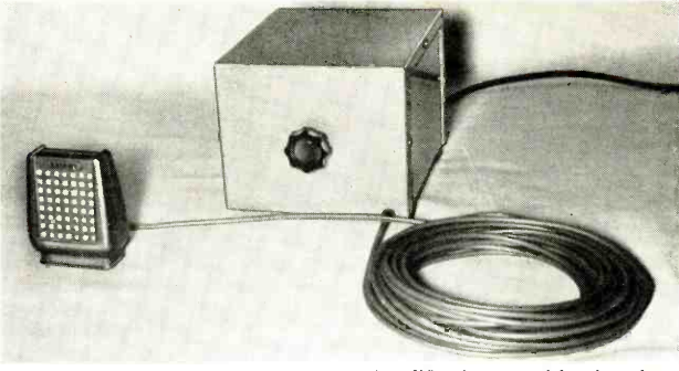
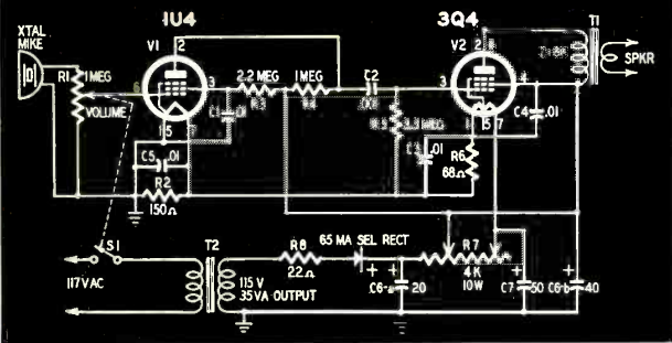
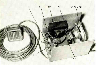
1959MayRadioElec2Sixty years ago this month, the May 1959 issue of Radio Electronics magazine showed how to construct this simple baby monitor. The device consisted of a two-tube (plus selenium rectifier) audio amplifier and speaker, with a remote crystal microphone at the end of a long cord. The mike could by placed over the baby’s crib, and the parents could keep their ears open in another room while dining or watching TV.

1959MayRadioElecSchematic


Communicating with Mars, 1919

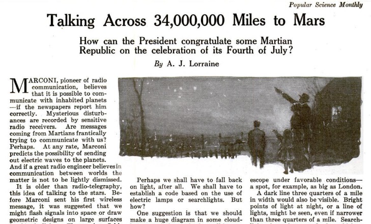
1919MayPSA hundred years ago this month, the May 1919 issue of Popular Science tackled the topic of communications with Mars. The magazine quoted Prof. Percival Lowell as saying that Mars is much older than Earth, and therefore it was reasonable to assume that the Martians had more time to evolve into creatures far superior to ourselves.

The magazine seemed to believe that radio waves wouldn’t do the trick. It noted that radio engineers on Earth require about 400 kilowatts to communicate 4000 miles. Thus, to make the millions of miles to the red planet, it looked bleak for wireless telegraphy.

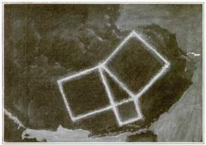
1919MayPS2A suggested alternative was to use light, and the magazine proposed setting up a lighted display of the Pythagorean theorem in the Sahara desert. “The Martians ought to recognize that Euclidean theorem, and reply with another. Picture would follow picture, until at last some kind of interstellar code would be established.”


Wartime Diversification for Radio Dealers

1944MayRadioRetailingWith manufacture of civilian radios being suspended for the duration of the war in 1942, radio dealers had to seek other avenues to augment their income. Of course, servicing sets became especially important, but dealers also diversified, and that often meant selling records. Shown here, on the cover of the Radio Retailing for May 1944 is the colorful record display at Paramus Tire Exchange, 150 E. Ridgewood Ave., Ridgewood, N.J. The unusual name for a radio store (much less a kids’ record store) is explained by the fact that owner Cy Jacoby had diversified into the radio business in the 1920’s. The article noted that he was one of the many automotive men who took on radio way back when lots of music merchants were not interested.”

The address proved to be a good one from a merchandising point of view. With the inability to sell radios (or tires) during the war, Jacoby put together this display. In fact, since the shop was wired with intercoms, he even put a speaker behind the display and would speak to kids as the looked at the display of books and records.

1944MayRadioRetailing2The magazine warned of another kind of diversification that was illegal. Some dealers were buying broken radios and using the parts to rebuild new sets. In some cases, the rebuilding consisted of putting a refurbished chassis into a new cabinet. But the magazine reported that the War Production Board had taken the position that this was illegal.

There had apparently been no prosecutions, although the magazine did note that there had been several cases of action taken against dealers who had converted automobile sets to home use. Presumably, making the conversion at home (as described at this post and this post) were OK, but a dealer could not do the conversion and sell the set.


Electric Fences: 1939

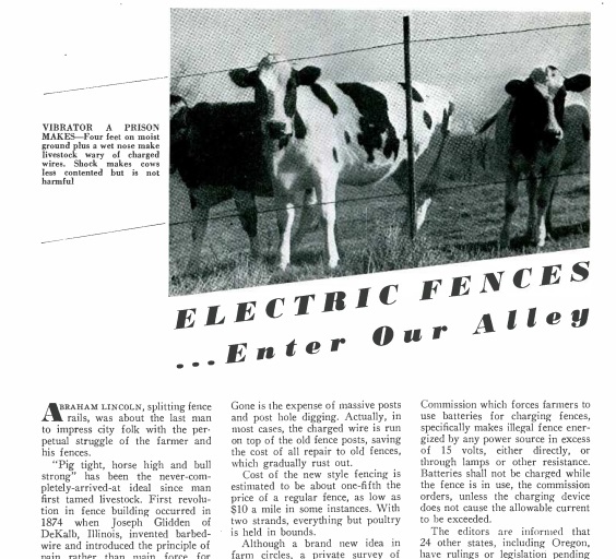
1939MayRadioRetailingFenceThe May 1939 issue of Radio Retailing offered some advice for radio men thinking of diversifying their business–the electric fence.  The magazine pointed out that a fence needs to be “pig tight, horse high, and bull strong,” but that this ideal has never been fully arrived at.  But a small electrical jolt will encourage all animals to shun the fence completely, at a much lower cost.

The article noted that the concept of an electric fence was fairly new, and that a Wisconsin survey showed that only about ten percent of the farmers in that state were employing them.  Many states had adopted regulations prohibiting the direct connection to the electrical mains, so even in areas of rural electrification, the dealer would be able to sell batteries and chargers to satisfy the need.


1959 Two Transistor Portable

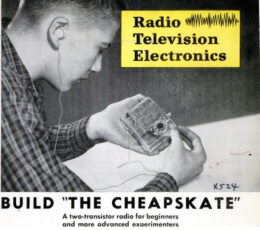
1959MayPM1Sixty years ago this month, the May 1959 issue of Popular Mechanics showed how to put together this two transistor receiver. While within the capabilities of the beginner, the set was a good performer. According to the article, the set was capable of pulling in stations 10-15 miles away with only the built-in antenna.

The RF amplification was handled by a 2N168A transistor. It operated as a regenerative amplifier, with a 1N66 diode serving as detector. The audio was then fed back to the same transistor, which was “reflexed” to serve as the first AF stage. A 2N170 transistor served as a second stage of audio amplification to drive the high-impedance earphone. The set was powered by four penlite cells wired in series.

1959MayPM2


Electronics Quiz from 1959

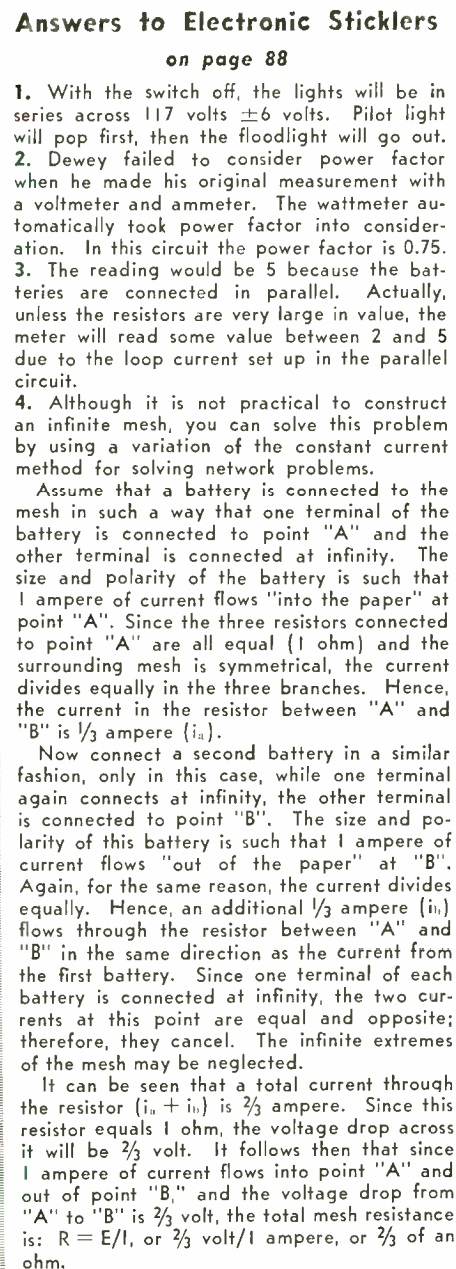
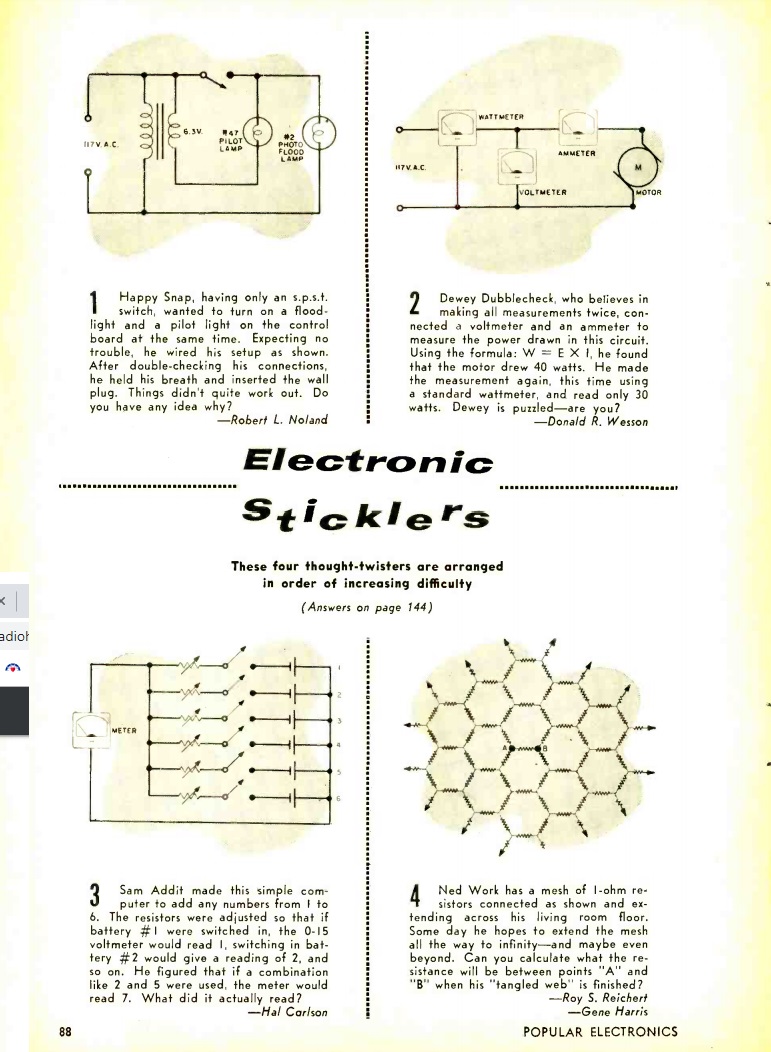
1959MayPEquizSixty years ago this month, the May 1959 issue of Popular Electronics contained these electronic brain teasers. We’re confident that most of our readers can figure them out, but just in case, we’ll show the answers tomorrow.

If you need a larger version, from most browsers, click twice on the image above.


1969 Two Tube Superhet/Regen

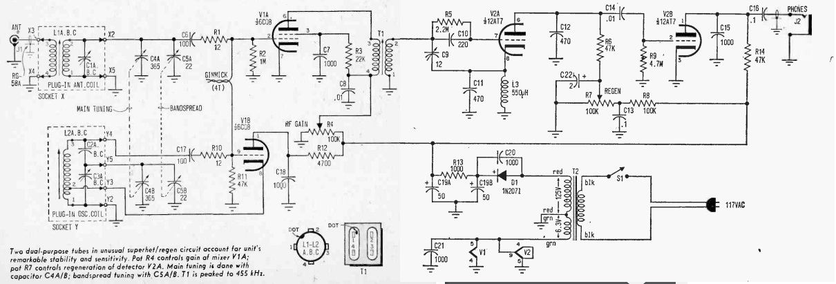
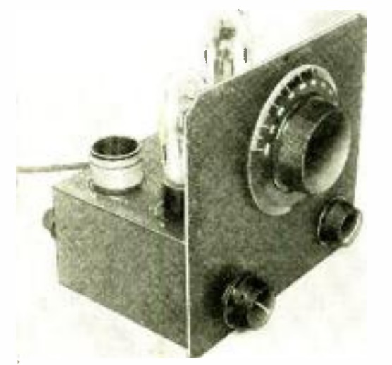
1969MayEE1Fifty years ago this month, the May-June 1969 issue of Elementary Electronics showed how to put together this two-tube receiver. The set covered 1.7-30 MHz with plug-in coils. And despite having only two tubes, it had excellent performance thanks to its design, which combined a superheterodyne and regenerative receiver.

The set used two dual tubes. A 6CQ8 served as mixer and IF amplifier, with a 12AT7 serving as regenerative detector and audio amplifier. The power supply consisted of transformer and solid-state diode.

1969MayEEschematic


1934 Two Tube Regenerative Shortwave Receiver

1934MaySWcraft

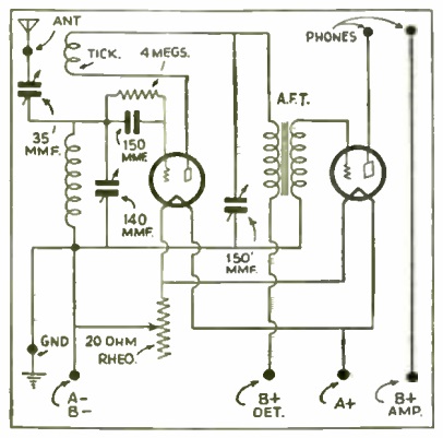
This handsome little two-tube shortwave receiver is described in the May 1934 issue of Short Wave Craft magazine. The circuit was designed by the National Radio Distributing Co., which presumably had all of the parts for sale, and used two type 30 tubes. A 45-volt B battery was sufficient for normal reception, but to pull in the weak signals, it was recommended to use 90 volts for the amplifier stage. In addition to the tuning dial, two other controls were visible on the front panel. One was a variable capacitor for adjusting regeneration, and the other was a rheostat for setting the filament voltage.

A well-insulated antenna of 45-100 feet was recommended.

1934MaySWcraftSchematic


Eico 720 Transmitter, 1959

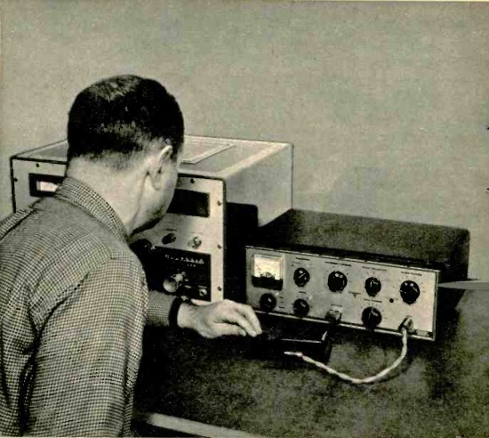
1959MayEISixty years ago this month, the May 1959 issue of Electronics Illustrated carried a review for the then-new Eico 720 transmitter.

The reviewer noted that the kit could be assembled in a week of evenings, and was within the capabilities of the beginning kit builder. The set had a maximum input power of 90 watts, but the plate current meter had a red line indicating the 75 watt limit for novices, the kit’s primary market. The review noted that the transmitter ran cool, despite its compact size. The output filtering was especially lauded, as the transmitter was well protected against television interference.

The kit sold for $79.95, with the wired version selling for $119.95. The review concluded by declaring the 720 a Good Buy for either the novice or the veteran ham.

For a look at a remarkably well preserved specimen, see this link.