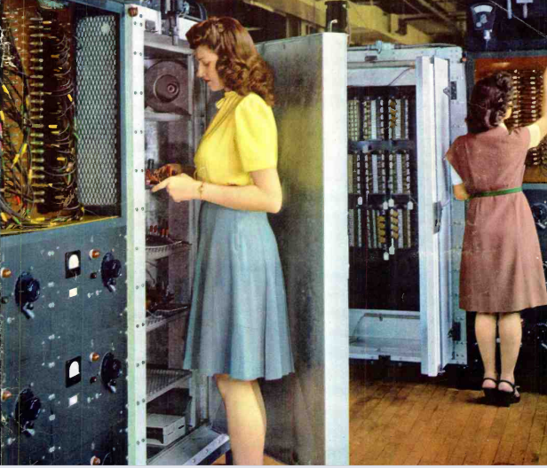
 Eighty years ago, these workers are testing mica and paper capacitors that rolled off the assembly line of Sangamo Electric Co., Springfield, Ilinois. The photo appeared on the cover of Radio News, June 1946.

Eighty years ago, these workers are testing mica and paper capacitors that rolled off the assembly line of Sangamo Electric Co., Springfield, Ilinois. The photo appeared on the cover of Radio News, June 1946.
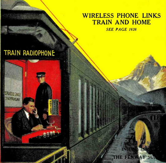 One hundred years ago, the Weimar Republic was at its peak, although four years earlier, the New York Times had first reported the potential danger from a popular idol with the capacity of swaying crowds to his will. But this German citizen is making use of the latest in technology, namely, being able to make or receive a phone call from a moving train, and the June 1946 issue of Radio News detailed the system in use by the German railroads.
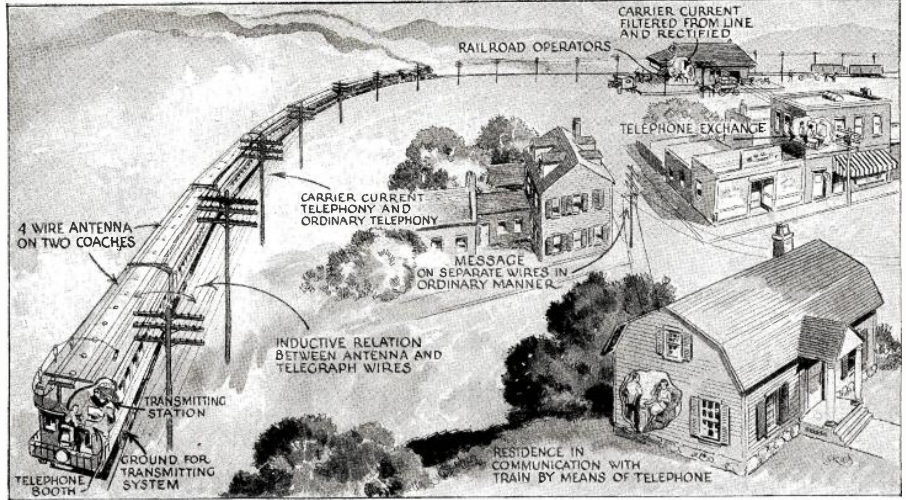
The phone relied upon a carrier current hookup. There was an antenna on the rail car, and the signal was carried by the telegraph wires that ran along the track. An operator at the station connected calls to the wired phone system, and calls could be placed anywhere with long distance service.
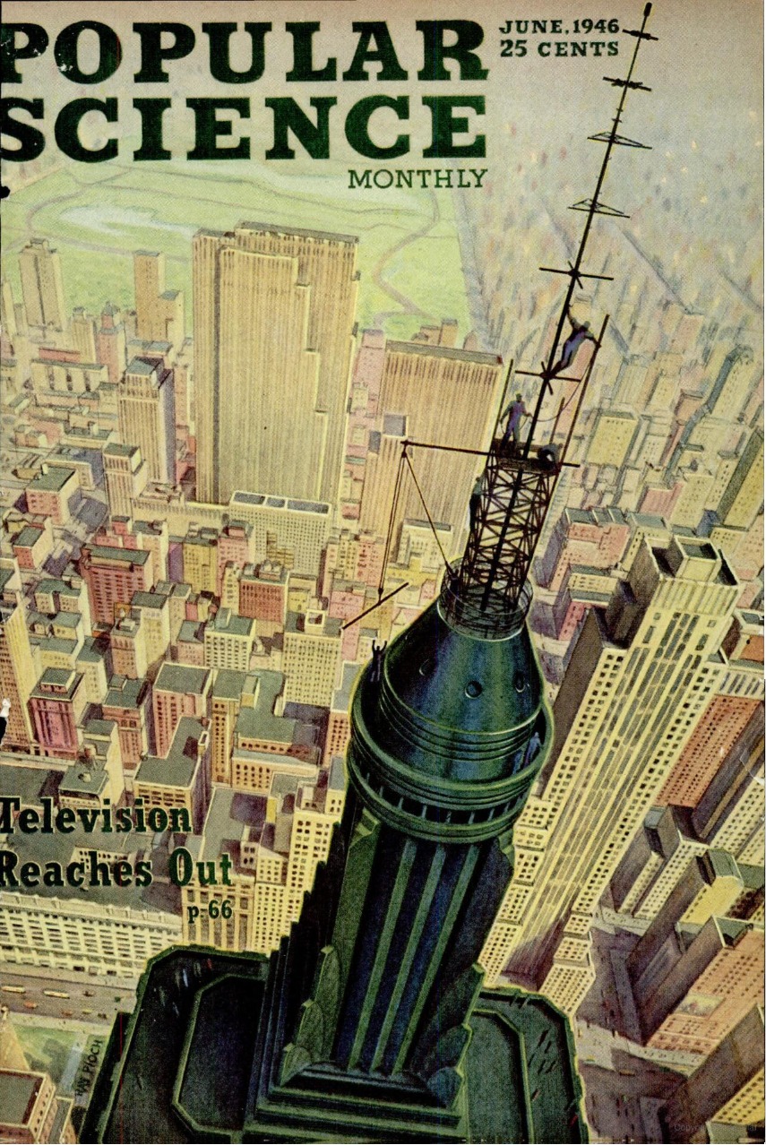 Eighty years ago, there were about 10,000 families in the United States with television, but it was rapidly growing. They would soon be guaranteed four hours per day of programming, as the FCC was about to adopt rules conditioning licenses on providing 28 hours per week.
The June 1946 issue of Popular Science reported on the state of television in the United States, and the cover picture showed the transmitting towers of WNBT atop the Empire State Building. Thirty feet had been added to the building, and with gain antennas, the station boasted a range of 60-70 miles. The next big event was said to be the Louis-Conn fight on June 19, which was to be telecast.
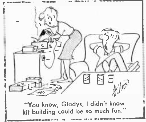 Sixty years ago, some would have considered soldering to be a “macho” activity. This gentlemen, however, shown in the June 1966 issue of Radio-TV Experimenter, was more progressive, and he realized that Gladys probably had better eye-hand coordination than he did (especially considering those beer cans on the table in front of him). I suspect that as soon as the kit was complete, it worked flawlessly.
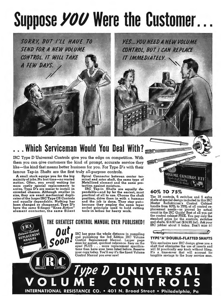 I don’t envy the poor radio serviceman shown in the left illustration, in the June 1941 issue of Radio Retailing. That customer doesn’t look very happy. If the poor guy got drafted the next year, the drill sergeant couldn’t scare him any more than she did. She was going to miss her favorite programs for a few days, and it looks like she’s taking her wrath out on him.
But the customer on the right is happy. She would be able to listen to her programs immediately. The difference was that the dealer on the right stocked a kit from the International Resistance Company, 401 N. Broad Street, Philadelphia.
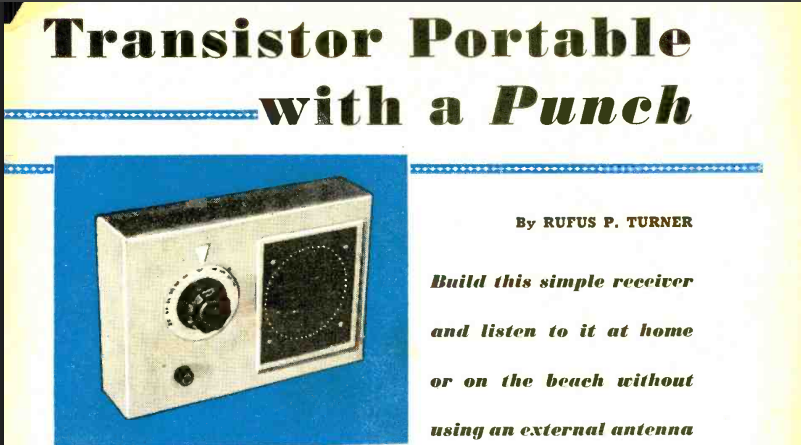
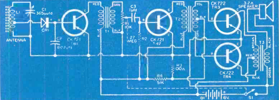
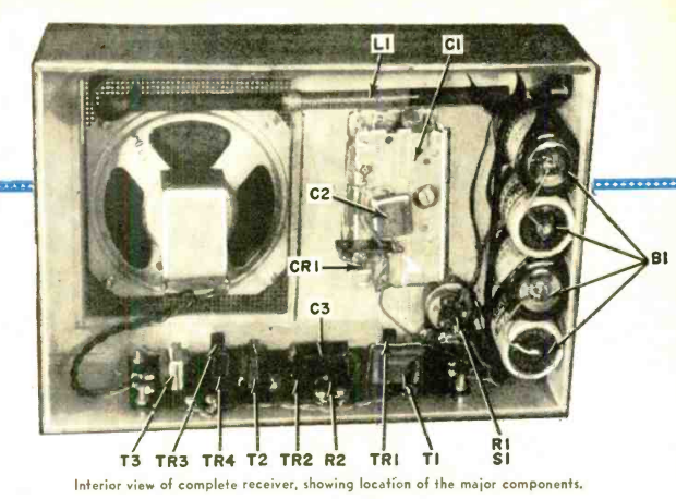 If you wanted to be the first on your block to have a transistor radio seventy years ago, one good way to meet that goal would be to build the one described in the May 1956 issue of Popular Electronics. It was said to pull in local stations with loudspeaker volume with no external antenna. It consisted basically of a crystal set followed by four stages of audio amplification.
Crystal sets often have very wide tuning, due to the detector loading down the tuned circuit and reducing the Q factor. In this case, however, the coil is tapped to reduce this effect.
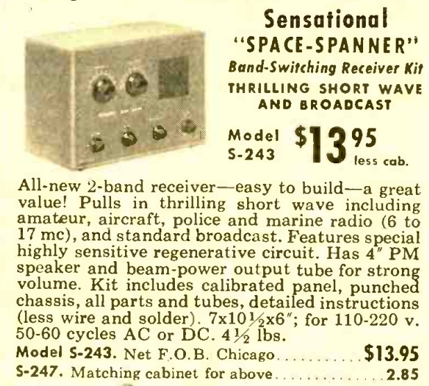 Seventy years ago this month, the May 1956 issue of Popular Electronics carried this ad for the Allied Knight Kit Space Spanner receiver. The three-tube AC-DC set covered the broadcast band and 6-17 MHz shortwave. It included a 35W4 rectifier and 50C5 final audio amplifier. The heart of the set was a 12AT7 which served as regenerative detector and first stage audio amplifier.
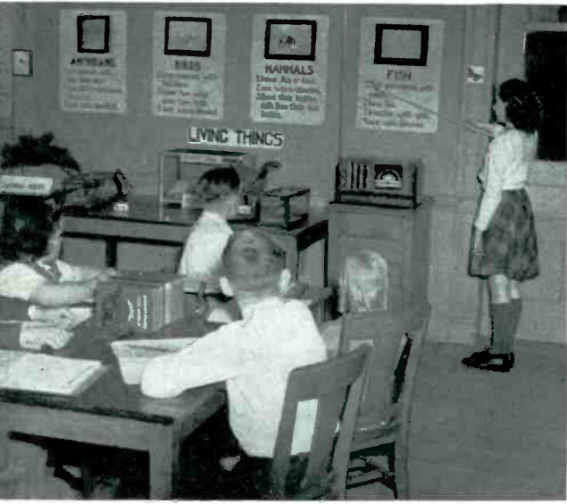 Eighty-five years ago, these Cleveland students are brushing up on the differences between amphibians, birds, mammals, and fish, thanks to their school system’s progressive use of radio in the classroom. It had been experimenting with radio since 1925, and was one of the first three (the others were San Francisco and Beattyville, KY) to get an FM license to broadcast to schools. The receiver was from Stromberg-Carlson, and the broadcast lessons were supplemented with these charts.
The photo appeared in the May 1941 issue of Radio Retailing.
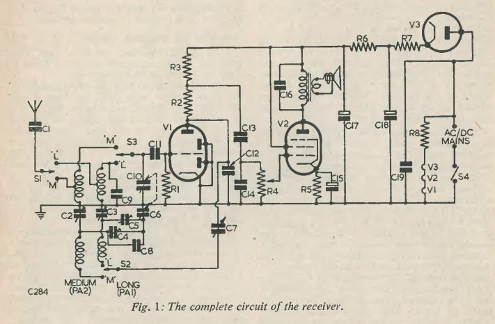
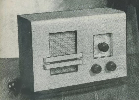 Seventy-five years ago this month, the May 1951 issue of Radio Constructor showed how to build this handsome three-tube (including rectifier) broadcast receiver. It covered both mediumwave and longwave (1225-2000 meters). A 15-foot antenna would pull in the mediumwave broadcasts, as well as the BBC Light Program and Radio Luxembourg on the longwave band. The detector was regenerative, and the author had to work out some tricks to keep the regeneration (or reaction, as they called it) stable even if the line voltage varied.
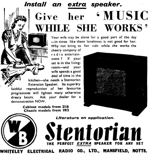 Eighty-five years ago, Britain was at war, but that didn’t mean that the British housewife couldn’t enjoy a little music while she worked. If your radio was in the living room, she was spending time working in the kitchen. The perfect solution was the addition of an extension speaker. She could then pass the otherwise dreary hours listening to her favorite programs. This ad for Stentorian speakers appeared in Practical Wireless, May 1941.