 We were recently passing through the Badger State on the way home from the Michigan QSO Party, and decided that the trip warranted a slight detour through Wisconsin Dells, one of the state’s most famous tourist destinations. The main attraction is the scenic gorge along the Wisconsin River, but seemingly since time immemorial, the town has been the home to many tourist attractions. These include destination-class water parks, but also a number of more kitschy “tourist traps.” (And when we say tourist trap, we mean that in the kindest possible sense. For example, we consider Wall Drug, a beloved national landmark, to also be a tourist trap.)
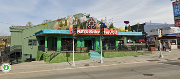
In my opinion, the best tourist trap in Wisconsin Dells is Ripley’s Believe It Or Not. It is billed as an “Odditorium,” and features a myriad of artifacts of the odd or unusual. I have to admit that I’ve always been a sucker for Ripley’s. As a kid, we didn’t have the daily cartoon feature in our newspaper, but it was a well-known brand. My family visited a similar museum in California, and Believe It Or Not books were readily available. For example, I owned a copy of the 14th Series, shown here. The egg shown on the cover illustrates the fact that if you hold an egg thusly (on the fingers, and not on the palm) and try to crush it with your fingers, it is impossible.
The preface of the book included a number of interesting facts about the number 14. The one that sticks with me over the years was about the French surname “Quatorze.” Like many surnames, this one represented an occupation. And the original Monsieur Quatorze was a professional 14th guest. If you were holding a dinner party and discovered to your horror that you had an unlucky 13 guests, you would just call Monsieur Quatorze, who would save the day. It’s a good job if you can get it, believe it or not. As a space filler, Ripley sometimes included unusual names found on grave stones, and this book contained the grave of Green Bean, found at the Bean family cemetery.
Now that we have the Internet, we can verify that there are two Green Bean graves, one of which is unmarked, although neither is located at the Bean family cemetery.
It had been at least ten years since I visited the Wisconsin Dells Ripley museum. It appears that they’re constantly making changes, and it did appear to be completely different from what I had experienced before. While the museum did cater to all ages, the modern version is probably more appropriate for young children than it previously was. In the past, the focus was more on things that younger children might have found scary. While they are still there (such as what is probably the most famous artifact, the shrunken head), they are not displayed quite as prominently. Also, the main mode of getting to the lower level of the museum (where most exhibits are located) consists of slides. There is also a stairway for older fans who don’t wish to slide. While it is not prominent, there is apparently an elevator, so all of the museum, other than a couple of very small portions, are fully accessible to persons with disabilities.) There’s also a ball pit tunnel, and guests are encouraged to touch all of the exhibits (unless they’re behind plexiglass, such as the shrunken head). So even though adults will find the museum good for an hour or two of browsing, even young kids will have fun.
The museum isn’t particularly cheap. The admission for adults over 10 years old is $29.11, and $21.83 for children 3-9. Despite a valiant search on my part, there don’t appear to be any discounts or coupon codes. (There are a couple of package deals to visit Ripley’s and other attractions owned by the same franchisee.) But it’s still a good value, as those of all ages will find themselves entertained and educated for a couple of hours.
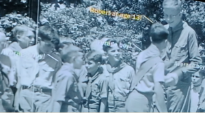 We, of course, scoured the museum looking for oddities relating to radio history. Unfortunately, we are sad to report that we didn’t find any. For that, you’ll need to keep following this blog. I did learn one interesting fact, however, about one of the topics that sometimes discuss, namely, Scouting. There was a life-size replica of the tallest human to ever live, Robert Wardlow. What I didn’t know was that Wardlow was a Boy Scout, or to be specific, the tallest Boy Scout in history, since he was 7’4″ as a 13-year-old Scout.
If your travels take you to Wisconsin Dells, the Odditorium is worth a visit. If, like us, you were just passing through the area on Interstate 90-94, it’s worth stopping for a couple of hours. And if you are making the Dells a destination, it’s certainly worth including this attraction.
Amazon links on this site are affiliate links, meaning that this site earns a small commission if you make a purchase after using the link.
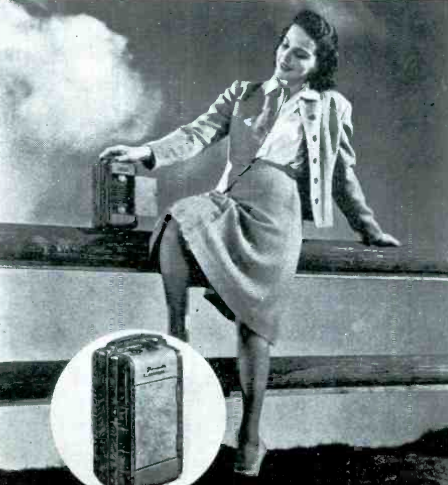
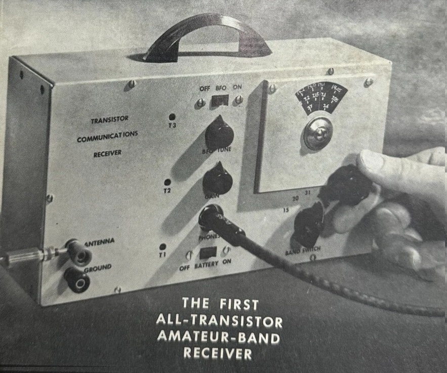 Seventy years ago this month, the May 1956 issue of QST featured what it dubbed the first all-transistor amateur-band receiver, handsomely housed in this 10 x 5-1/2 x 3 inch cabinet. Designed by Carl Heinen, W0MCN, the 7-transistor set covered the 15 through 80 meter ham bands. The editors of the magazine noted that it was not a toy, but instead a set that compared favorably to the lower-priced communications receivers on the market.