Author Archives: clem.law@usa.net

Hoosier Girls Build Radio, 1922

DorotheaAliceHanna

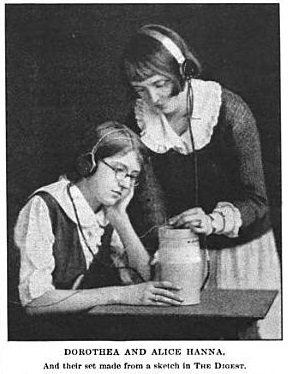
Shown here are Dorothea and Alice Hanna of Indianapolis, Indiana, ages 13 and 15, along with the radio they constructed according to plans published in the April 22, 1922 edition of Literary Digest. The set was designed by 21-year-old James Leo McLaughlin of New York, shown below along with his radio.SimpleXtalSet

In a letter to the magazine, the girls’ father reported that they arrived home from school with the copy of the magazine, and immediately pooled their allowances and set off to purchase the required parts at an electric store and stationery store. They had the set assembled by 6 PM. The next afternoon, “refuing all help from father or brother” they had the aerial and ground installed. They were soon receiving programs, “when many expensive sets reported only fragments or no sounds at all.”

The father reported that the girls had never studied physics and had never seen or heard wireless. Their sole assistance was driving the ground pipe into the ground and securing the switch to the side of the house.

The father reported that the girls’ total expenditure was $6.30, which he concluded was well invested.


Click Here For Today’s Ripley’s Believe It Or Not Cartoon


1915 Radio Controlled Boat


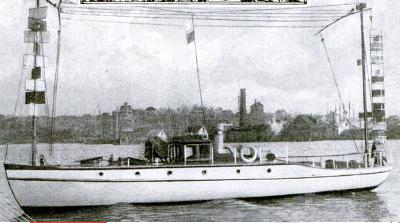
Nautalia1915A hundred years ago, Popular Mechanics, January 1915, shows the Natalia, a radio controlled boat, and reports a test in which the unmanned vessel sailed from Boston Harbor 28 miles into open seas, controlled only by the wireless transmitter located as far as 20 miles from the boat.

As a backup, the boat could be controlled by light, since it was equipped with selenium cells which responded to light beams. While the details of this Army-Navy experminet were not revealed, it was believed that the receiver aboard the boat was equipped with a new type of coherer. The boat was equipped with a motor which actuated the boat’s steering wheel.

Click Here For Today’s Ripley’s Believe It Or Not Cartoon


1965 Emergency Crystal Set from Boys’ Life

BL1965XtalSet

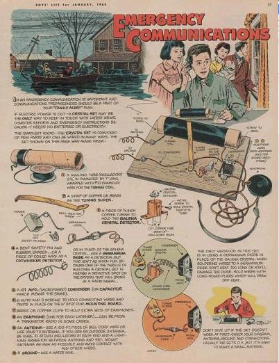
In an earlier post, we looked at a one-transistor CONELRAD receiver featured in Boys’ Life magazine in 1956.  And today, we look at a simpler variation on the same theme, this time from 50 years ago this month, in Boys’ Life magazine January 1965.

Once again, the Scout’s obligation to Be Prepared is inspiration for this electronic construction article.  It’s a basic crystal set, but the focus is on being prepared, under the title EMERGENCY COMMUNICATIONS.

A terrified family, clad in pajamas, is apparently confronting rising flood waters. The text warns that “in an emergency, communication is important and communications preparedness should be a part of your ‘family alert’ plan.” It goes on to warn that if electric power is out, a crystal set may be the only way to keep in touch with latest news, disaster reports, and emergency instructions.

The page details how to build the radio using a galena detector with either a safety pin or piece of coiled wire. It acknowledges that a germanium diode can also be used but “isn’t as much fun” because it lacks the thrill of finding a sensitive spot on the crystal.

No author is listed, and the construction details are a bit lacking in detail. (In particular, no mention is made that the insulation has to be removed from the top of the coil in order to contact the slider.)

If you were a Scout 50 years ago, you were prepared. And a flood was nothing. You needed the additional thrill of finding the sweet spot on the crystal.

All of the parts for this set are readily obtainable.  If you’re having trouble finding any, you can find them on my crystal set parts page.


US Embassy in Tokyo After Pearl Harbor: The Secret Radio

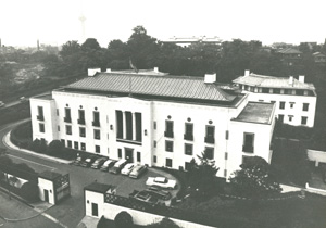
US Embassy Tokyo, 1931 photo.  (US Gov't photo).

US Embassy Tokyo, 1931 photo. (US Gov’t photo).

The website of the Association for Diplomatic Studies and Training contains a very interesting account of life in the U.S. Embassy in Tokyo after Japan’s attack on Pearl Harbor.  It is the reminiscences of Robaert A. Fearey, who served as personal secretary to Joseph Grew, the U.S. Ambassador to Japan from 1932-41.

Fearey had recently graduated from college, and had a 4-F draft status due to eye problems.  He had been recommended by his college for the assignment, and sailed for Japan in early 1941.  On the morning of December 8, he, along with the rest of the embassy staff, heard of the attack on Pearl Harbor.  Late in the morning, a car from the Foreign Ministry arrived with the official notification.

The staff of the embassy was interned in the embassy compound until June, when they were repatriated on a well-lighted Japanese ship via Mozambique.  The journalists with whom they sailed home had been assumed to be spies and were tortured.  The embassy staff, however, was allowed to remain relatively unmolested on the embassy grounds.  The staff was even able to witness the Doolittle Raid of April 18, 1942.

One condition imposed by the Japanese was that the embassy was not allowed to retain any radio transmitter or receiver.  The embassy didn’t have any transmitter, instead relying on commercial telegraph.  The ambassador protested the seizure of radio receivers, but to little avail.  The Japanese searched the compound for radios and seized them.

But Fearey reports that he kept one radio:

Again demonstrating youthful indiscretion, I went back to my apartment and effectively hid a tiny pocket radio which a college housemate and amateur radio expert had made for me and which I had brought along to Japan. The radio was about five inches long, three inches wide and three-quarters of an inch thick and had what my friend had told me might be two of the smallest tubes ever made. I carried it inside the upper pocket of my jacket, with holes cut in the pocket so I could reach in to turn the control knobs. a thin wire ran
up under the back of my coat to a small, almost invisible ear plug. With this device, I had been able, unbeknownst to anyone, to listen to the radio during classes at college and even when riding my motorcycle. In Japan, I had tried it out a few times and had no
trouble receiving Japanese language stations. In our current predicament, I thought it might be a useful source of information, and in any case, I did not want to lose it. The searchers never found it, and it did prove to be a moderately useful source of information
until the tiny batteries wore out. I brought it back to the States on the repatriation ship.

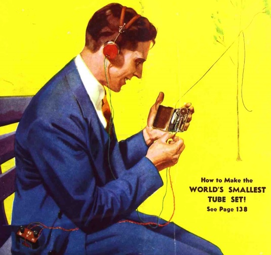
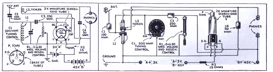
It seems likely that the radio in question was similar to the one shown here on the cover of the September 1935 issue of Radio Craft magazine.
SmallestRadio1935

The description of Fearey’s clandestine radio seems to match up with the description of the 1935 project.  The 1935 receiver was one tube, and Fearey reports that his contained two tubes.  So chances are, the unnamed builder of Fearey’s set added an extra stage of amplification.  But it seems to be the same general design.

Fearey reports the size of his radio as being about 5 by 3 by 3/4 inch, with “two of the smallest tubes ever made.” The Radio Craft design doesn’t specify the dimensions, but reports that it was built in a bakelite cigarette case designed to hold ten cigarettes. The radio in the article uses an English tube which does appear to be the smallest in production at that time.

And significantly, the construction article notes that crystal earphones are used. While the article shows the set used with a pair of headphones, a crystal earphone was available at that time, as noted in the article. The article calls for 25-30 feet of wire for the antenna, but with a strong station and/or the additional tube, the use of the smaller antenna described by Fearey seems plausible.

The schematic and pictorial diagrams of the Radio Craft set appear below.
SmallestRadio1935Diagram

Fearey’s account is also available as a web page with additional illustrations.


Click Here For Today’s Ripley’s Believe It Or Not Cartoon


Twin Cities Television in 1950

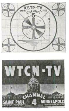
1950stationID65 years ago, the January 1950 issue of Radio Craft magazine carried a complete roster of U.S. television stations on the air as of November 15, 1949, and included a copy of the identification slides used by each station. By that time, Minnesota had two stations on the air. The test pattern for KSTP-TV, channel 5, which came on the air in 1948, is shown here. Also shown is the station identification slide for WTCN-TV, as channel 4 was then known.

Channel 4 came on the air on July 1, 1949, originally as WTCN-TV. Its main affiliation was with ABC, but it also carried CBS and DuMont programs.

By the end of 1949, there were 60,000 television sets in service in the Twin Cities able to tune in to the two stations. In 1949, weatherman Bud Kraehling joined the station where he stayed until his retirement in 1996. 1950 saw newscaster Dave Moore join the station’s staff. In 1950, the coaxial cable arrived in the Twin Cities, allowing the stations to broadcast live network programming. Minnesota’s connection to the national networks was actually through a coaxial cable to Des Moines, Iowa, which was in turn linked by radio relays to Chicago.

Those of us who grew up in the 1960’s and 1970’s recognize the WTCN call letters as belonging further up the dial on channel 11. In 1952, the owners of channel 4 and WTCN radio sold the radio station and merged with WCCO Radio, and the station became WCCO-TV. The same year, an application was filed with the FCC for a construction permit for channel 11. This became WMIN-TV, and in 1953, WTCN-TV showed up again, also on channel 11. The two stations cooperatively shared airtime and transmission facilities. WTCN-TV studios were at the Calhoun Beach Hotel (the location, of course, of Grandma Lumpit’s Boardinghouse), where they remained until the 1970’s. WMIN-TV sold out in 1954, at which point channel 11 became WTCN-TV full time.

The WTCN call letters date back originally to 1934, when the predecessor of WWTC radio (currently at 1280 on the AM dial) was purchased by the Minneapolis and St. Paul newspapers. The WTCN call sign stood for Twin City Newspapers. Channel 11 had no connection with the earlier radio station other than the use of the historic call letters, which remained in use until 1985, when they became WUSA, and then KARE in 1986.

References

Pavek Museum, Twin Cities Television Milestones


Click Here For Today’s Ripley’s Believe It Or Not Cartoon



1956 Boys’ Life CONELRAD Receiver

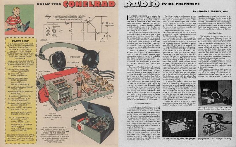
BLConelradRadio

In the mid-1950’s, a transistor radio was an expensive luxury. This presented a problem for an impecunious Boy Scout who wanted to Be Prepared for anything. In the words of Boys’ Life magazine for January 1956, “in case of enemy attack, it is assumed that power lines will be down, and battery-operated radios would be a necessity. But batteries wear out. So what you need for Conelrad service is a receiver that doesn’t use B batteries, yet will produce a usable signal when needed.”

The article pointed out that a crystal set might be pressed into service, but wouldn’t produce very loud signals. Fortunately, Boys’ Life had a solution to the problem, in the form of this one transistor set that was well within the construction abilities and budget of a Scout. The set shown here would run on two penlight cells with clear headphone volume for well over a thousand hours. And in a dire emergency, since the set consisted of a crystal detector with one-transistor audio amplifier, the article gave instructions on how to bypass the amplifier and simply use it as a crystal set with reduced volume.

The set is build on a board, with instructions to mount it in a cigar box (painted black, according to the directions), which left ample room for storing the antenna wire, ground lead, and headphones. Since the set was designed for CONELRAD use, the article instructed to find the local broadcast stations closest to 640 and 1240 on the dial, tune them in, and then mark the dial position for future emergency use.

The circuit calls for a FS2500A transistor, which is a general purpose NPN transistor, apparently manufactured by Bogue, also known Germanium Products Corporation.  (See the substitution guide in the 1957 RCA Transistors and Semiconductor Diodes.)

The article was reprinted for a number of years in the Boys’ Life Radio and Signaling reprint booklet. Occasionally, the “Hobby Hows” column of Boys’ Life would answer a letter from a Scout asking where to find the plans for the receiver, who was directed to the reprint booklet. Therefore, I suspect more than a few scouts built one of these receivers, and I’m sure they were put to good use for entertainment purposes. The builders of these sets were undoubtedly the first kids on their block to own a transistor radio. Fortunately, none ever had to be used for the intended purpose of tuning in to CONELRAD alerts.

The author of the article was Howard G. McEntee, W2SI. McEntee was the author of the Radio Control Handbook, published by Gernsback Publications in 1955 and updated over the years.


Operation Cornflakes: Tampering With the Nazi Mail

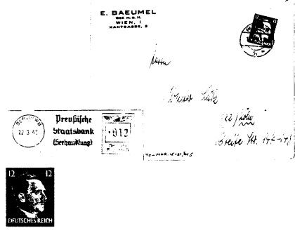
Forged envelopes and stamps, courtesy of CIA website.

Forged envelopes and stamps, courtesy of CIA website.

Seventy years ago today, January 5, 1945, Allied bombers engaged in an unusual attack. They bombed a mail train heading for Linz, Austria. The train was derailed, and mail was scattered around the area. More bombers then arrived and dropped mail bags appearing for all the world to be genuine Reichspost bags. Inside were about 3800 letters addressed to Germans, many of whom were the families of German soldiers who had been killed in action.

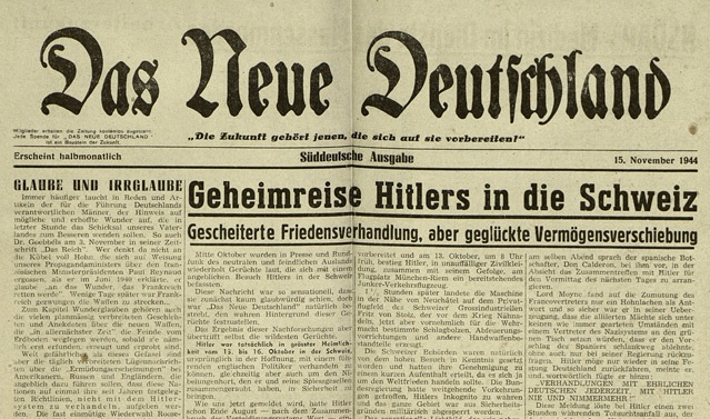
The plan was known as Operation Cornflakes. The return addresses on the letters were those of German firms, and the letters outwardly appeared to be normal business correspondence. However, the envelopes contained propaganda newspapers prepared by the U.S. Office of Strategic Services (OSS), including issues of Das Neue Deutschland, an example of which is shown below.

DasNeueDeutschland

The stamps, envelopes, and even the mail bags, had to be carefully forged to appear original to the postal workers who would handle them. While the program had no discernible effect, it was successful in that most of the propaganda letters were introduced into the German mails. After the train was bombed, German rail and postal workers dutifully picked up the scattered mail bags and sent them onward to their intended recipients.

The stamps and envelopes shown above are examples of some of the forgeries, courtesy of the CIA website. To ensure that the propaganda would blend in with the normal mail, the OSS consulted German POW’s who had worked for the post office. The details of the cancellations had to match what was in use in the cities from which the mail had purportedly originated, and there had to be some semblance of mail being in the proper train for the town for which it was intended. German POW’s provided most of this information relating to the internal workings of the German mails.

Most of the mail was successfully delivered, but in one case, a sharp-eyed German postal worker noticed that the name of the company was misspelled on the return address. This, of course, resulted in that particular batch not being delivered.

References


Read More at Amazon

Click Here For Today’s Ripley’s Believe It Or Not Cartoon


Wartime 3-Tube Regenerative Receiver

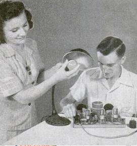
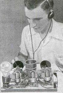
Jan45PMrcvrWartime parts shortages were a major inspiration for the design of this short wave receiver from the January 1945 issue of Popular Mechanics. The lamp isn’t there for decoration; it’s one of the parts.

The receiver used three identical tubes, the 6C5. It ran directly off house current. The three 6-volt filaments are run in series, and to avoid the need for a filament transformer, a 40-watt light bulb in series is used to drop the 110 volt house current to the 18 volts necessary to light the tubes. A standard household receptacle is mounted directly on the chasis, into which a desk lamp can be plugged. Another alternative was to mount the bulb directly on the chasis, using a lamp adapter plug.

Speaking of the chasis, the set is constructed on a literal breadboard, sourced from the nearby dime store. The coil form was also obtained at the dime store, in the form of a plastic drinking cup. The coil is wound with cotton-covered wire, held in place with fingernail polish.

Jan45PMrcvr2The two variable condensers, one for tuning and the other for regeneration, were scavenged from old broadcast receivers. For regeneration, only half of the 350 mF condenser is used. For tuning, the two sections of the 350 mF condenser are wired in series, rather than parallel, resulting in 88 mF, which is better suited to the 25 and 31 meter bands the set tunes. An additional five resistors and five capacitors round out the parts list.

One of the 6C5 tubes is used as a rectifier, one serves as the regenerative detector, and the final one serves as an audio amplifier. In the 1943 Allied Radio catalog, the tubes are available for 56 cents each. The catalog notes that most glass tubes were available in limited quantities. However, it noted that the metal tubes were generally available only to high priority customers.

Click Here For Today’s Ripley’s Believe It Or Not Cartoon


Canadian Wartime Nickel Contains Morse Code

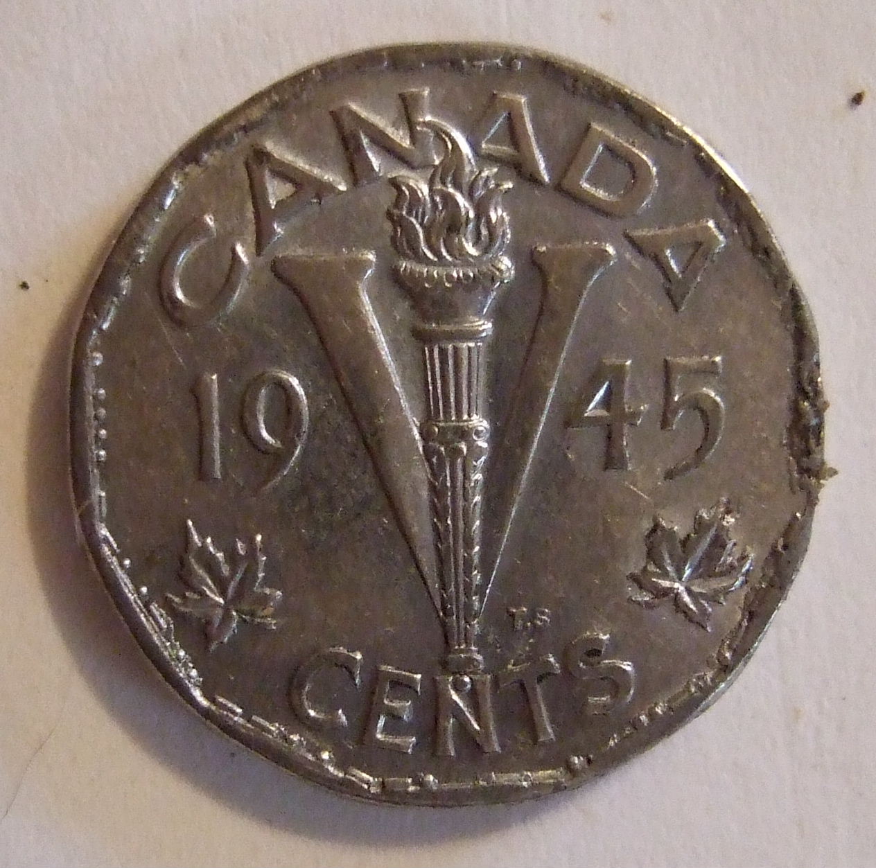
The 1943-45 Canadian five cent coin, known as the “Victory Nickel,” is unusual in that it contains Morse Code.  Most Canadians were unaware that they were carrying a Morse message in their pocket, since the code is discernible only upon close examination with a magnifying glass.  It is partially visible on the image shown here.  It’s on the reverse of the coin, and runs clockwise along the edge.  It begins just to the left of the letter “N” in the word “CENTS”.

The beaver design currently appearing on the coin first appeared in 1937, but the coin was redesigned during the war.  The reverse featured the letter V, with a dual significance.  In addition to being the Roman Numeral for five (which was used on the U.S. Liberty nickel from 1883-1912), it was also the symbol of victory.

And with little fanfare, it also included the message, in Morse Code, “WE WIN WHEN WE WORK WILLINGLY.”

The Canadian Mint re-issued the design in 2005, dated 1945-2005, to commemorate the 60th anniversary of the end of the war.  However, the 2005 design did not include the Morse Code inscription.

Specimens of the coin in which the full message is legible are fairly uncommon.  Most were made of steel, plated with nickel.  The sheets were plated before the blanks were cut out, resulting in the edges being unplated.  This has caused most of them to rust around the edges, making the Morse Code illegible.  In the example shown above, the words “WE WHEN WHEN WE” are very legible, but most of the rest of the message is impossible to make out.

The 1943 coin was made of tombac (a brass alloy), and the message is more likely to be legible on specimens from that year.

References

Canadian Mint, Five Cents.

QST, January 1945, page 48.


The First Home Computer, 40 Years Ago

Jan1975PE

The home computer is 40 years old. The one that appeared in January 1975 issue of Popular Electronics. Used copies of this issue typically fetch about a hundred dollars on eBay, but fortunately, a full scan of the issue is available at AmericanRadioHistory.com.  The January issue carried a summary of the computer and some of the construction details. The February issue included an introduction to programming it.

The January issue carried an editorial announcing that the home computer was here. It correctly noted, “for many years, we’ve been reading and hearing about how computers will one day be a household item. Therefore, we’re especially proud to present in this issue the first commercial type of minicomputer project ever published that’s priced within reach of many households–the Altair 8800, with an under-$400 complete kit cost, including cabinet.”

The construction article billed the computer as the “Popular Electronics/MITS Altair 8800.” It was built around an Intel 8080 CPU chip, which could handle up to 78 instructions. The construction article did contain a parts list, but not full PC board templates. Those were available by mail, but it’s likely that most builders took advantage of the computer’s being available in kit form for $397, or fully assembled for $398 from MITS, Inc.

The basic computer came with 256 words of memory, with up to 65,000 being available through add-ons. The parts list called for a 2 MHz crystal, indicating the processor’s speed.

The January article suggested some possible applications for the computer, such as use as a programmable scientific calculator, machine controller, or automatic drafting machine. The February issue included the basics of programming the computer, along with a sample program to add the contents of two of the registers and store them in a third.

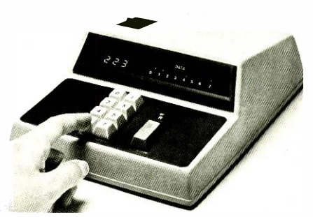
Dec1974PETerminalProgramming was accomplished from the spring-loaded switches on the front panel. Another possibility for programming the computer was to use a computer terminal, and the article suggests the design that had appeared in the December 1974 issue, shown here. It’s probably not the mental image that would come to mind upon hearing the phrase “computer terminal.” It’s simply a method of sending an octal code to the computer, and receiving one back.

It was a year or two after the computer first appeared that I first saw one. When I saw it, the builder hadn’t really come up with anything for it to do. He was working on interfacing it with a teletype machine, and at that point, all he could make it do was have it output the character associated with a particular ASCII code. In other words, he entered a number using the front panel switches, and it printed out the corresponding letter. I remember not being too impressed, but I guess I did realize that at some point, I might have a computer in my house.


Click Here For Today’s Ripley’s Believe It Or Not Cartoon