It’s almost that time of year again to shop for back-to-school supplies. Back in my day, that was a relatively straightforward proposition. Parents went to the store to purchase supplies such as crayons, pens, pencils, and notebooks. Especially as kids got older, the family’s shopping list was sometimes supplemented by a list from the teacher. That list often included the more esoteric items such as protractors,
 compasses, and other specialty items. It was clearly understood, however, that the supplies that each child brought to school were intended for that child. In fact, it was frequently requested that the items be marked with the child’s name.

 At some point, an enterprising teacher came up with the idea of requesting a few communal supplies. This probably started innocently enough, when some teacher noticed that stores were selling certain items as loss leaders. For example, a discount store might advertise that it was selling glue sticks for 5 cents, a price well below cost, and much less expensive than the school’s normal supplier.
So if a teacher needed a supply of glue sticks to last the year, asking the parents to buy a few made perfect economic sense: Each parent spent only a few pennies to buy a few extra glue sticks. This saved the school a larger amount of money by not having to buy at the higher price. It was a win-win situation for all involved, except perhaps the store. But the store went in with its eyes wide open, fully realizing that they were going to lose money on the glue sticks.
Unfortunately, however, this whole system eventually got out of hand. The technique worked so well that the size of the lists kept getting larger and larger. And unfortunately, the list was no longer limited to loss leaders. Eventually, teachers began demanding specific brand name products, without regard to cost or availability. In fact, since the lists were public knowledge, retailers could be careful not to sell any of the listed items at a loss.
As a result, procuring all of the items on the list became a financial burden, to the point where some parents could no longer afford to purchase the full list. As a result, the children became either the “haves” or the “have nots.” Some children came from families that could afford the expensive designer label glue sticks. But other families could not. Chances are, all or most of the children would have been able to afford the cheap loss leaders. But some could not afford the expensive versions that were now demanded by the lists.
Perhaps correctly, someone noticed that this wasn’t fair: Some children came to school with all of the supplies. But some came with no supplies. At this point, a decision was made to make all supplies communal. Gone were the days when teachers recommended placing the child’s name on supplies. With the advent of communal school supplies, parents were now prohibited from labeling them with the child’s name. Children no longer had their own pencils. Instead, they brought the requested brand-name pencils to school, in accordance with their abilities. Then, the children helped themselves to the now free pencils in accordance with their perceived need.
Since some parents could no longer afford to buy the expensive designer brand names, the remaining parents were required to provide them in larger and larger quantities. This, in turn, resulted in a greater economic burden, meaning that the number of “have not” children kept increasing.

 Of course, the communal supplies generally aren’t as well cared for as personal property, further increasing the expense. And since parents are buying communal supplies anyway, the teacher naturally adds a few other needed communal items, such as Kleenex, cleaning supplies, and dry erase markers. For many of these items, the children (whose parents bought them) are not allowed to use them.
As with most forms of communism, this is not sustainable, and it will soon enter a death spiral as fewer and fewer parents can afford to purchase all of the required supplies. But in the meantime, the few remaining “have” parents are expected to purchase the items on the growing lists.
Eventually, there will be a rebellion. But in the meantime, you can ease some of the pain by taking advantage of the school lists at Walmart.com
 . You can search for your school by zip code and view the lists. In some cases, the expensive brand names won’t be available at Walmart. But if they are, you can purchase online, or at least do price comparison online. Since the prices are the same nationally, there’s less chance of a particular item’s price being manipulated because a local retailer knows it’s required by a local list. If you do purchase online, in most cases, you have the option of picking up your order at the store. I’ve used this service a number of times, and it works quite well. You simply go to the counter, show your ID, and your entire order is brought to you, without have to fight the crowds in the back to school aisles.
Links in this post are affiliate links, meaning that this website receives a commission if you order after viewing the link.

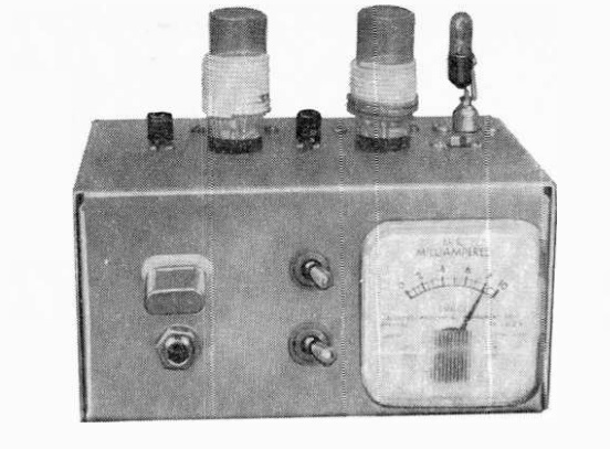 Sixty years ago this month, before QRP was cool, the August 1958 issue of Popular Electronics carried the plans for this QRP transmitter for 15, 11, and 10 meters. The set was dubbed the Semiconductor Space Spanner. The two-transistor transmitter had an input power of 96 milliwatts. The author, Don Stoner, W6TNS reported contacts all over the continent and as far away as Hawaii. While some of those contacts were pre-arranged, many were the result of a normal CQ.




 . You can search for your school by zip code and view the lists. In some cases, the expensive brand names won’t be available at Walmart. But if they are, you can purchase online, or at least do price comparison online. Since the prices are the same nationally, there’s less chance of a particular item’s price being manipulated because a local retailer knows it’s required by a local list. If you do purchase online, in most cases, you have the option of picking up your order at the store. I’ve used this service a number of times, and it works quite well. You simply go to the counter, show your ID, and your entire order is brought to you, without have to fight the crowds in the back to school aisles.