Monthly Archives: April 2021

1951 Two Tube Receiver

1951AprPM21951AprPM3
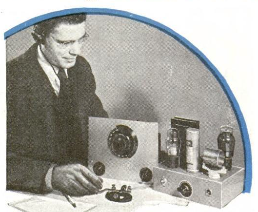
The September 1951 issue of Popular Mechanics showed how to put together this simple two-tube receiver. It was earmarked especially for the new ham, since it covered the 80 meter ham band. But it would also pull in a wider range of frequencies, including police calls and the 49 meter international broadcast band.

The timing of the article wasn’t a coincidence, since the circuit was specifically targeted at those interested in the Novice class amateur radio license. That new license, which required only a 5 word per minute code test, had just been announced by the FCC, which started issuing them on July 1, 1951. Armed with this receiver, and a key and buzzer, the prospective Novice would be able to pass the test with ease. The magazine promised that the October issue would include an accompanying transmitter.

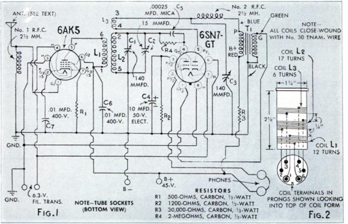
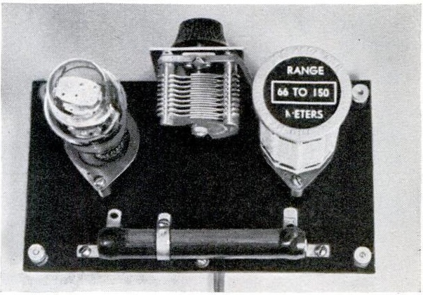
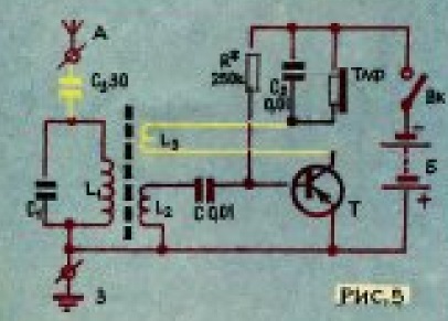
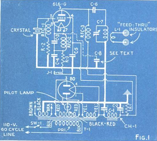
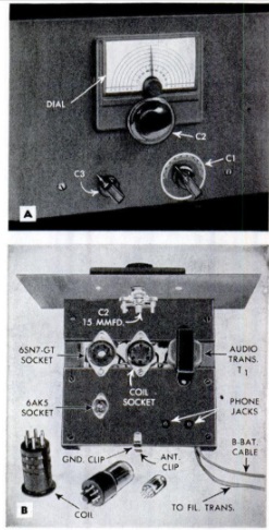
Construction was simple, as it used two pieces of hardwood mounted on wooden cleats. There was a gap between the two boards, allowing for easy mounting of the sockets for the two tubes and one plug-in coil. Power came from a 45 volt battery, but to prevent having to replace A batteries, a 6.3 volt transformer was used to light the filaments. No power switch was provided, and the magazine noted that a switch could be mounted somewhere on the operating table in line with the transformer.

The magazine recommended a 10-15 foot indoor antenna and ground for the two-tube regenerative set. One variable capacitor was used to control regeneration, with another one serving as the main tuning dial. The procedure for using the set was to advance the regeneration until the set came to life, and then tune the main tuning dial until 80 meter stations were heard. At that point, the larger bandspread dial would be used for tuning.

1951AprPM4


One Tube Radio Using Rectifier

1941AprilPSEighty years ago this month, the April 1941 issue of Popular Science showed this novel little one-tube receiver. Even though it’s basically a crystal set, it qualifies as a one-tube radio since it uses a rectifier tube, a 25Z5, in place of the crystal.

The article points out two things that might not be obvious. First of all, even though the set is running on AC power, there is no hint of 60 cycle hum. The electric power does nothing but heat the filament, and the heated cathode and plate serve as the detector, with no electrical connection to the power. The magazine also notes that it’s safe to use a ground connection, since there’s no direct connection.

Even though the filament normally runs on 25 volts, it should be under 6 volts in this circuit. An 80 watt resistor is used to drop the voltage, although I bet an incandescent light bulb could be used.

1941AprilPS2


1941 Prices: Western Auto

1941WesternAutoHere’s a snapshot of the cost of living from 80 years ago, on the eve of World War 2, from the April 16, 1941, issue of the Pittsburgh Press, courtesy of this ad for Western Auto Stores.  (For a larger image, from most browsers, click twice on the image.)

According to this inflation calculator, one dollar in 1941 was the equivalent of $18.02 in 2021 dollars. Here are some representative prices, with the modern equivalent in parenthesis:

Western had its own brand of radios, Truetone. A portable, which could operate on battery or household current, sold for $14.45 ($260.39), not including the battery. A single-unit car radio, with pushbutton tuning, could be had for the same price. A three-piece unit sold for $27.95 ($503.66), which included installation. The six-tube set had a chassis that mounted out of the way, with separate control unit and speaker.  Whichever car radio someone bought in 1941, there’s a good chance that they would be taking it inside to listen to when gas rationing meant the car spent most of its time in the garage.

Spark plugs would set you back a quarter ($4.50), but they were guaranteed for 10,000 miles. Fan belts started at 34 cents ($6.13). A new battery for the car would be $4.45 ($80.19) and was guaranteed for two years. A bicycle was $18.75 ($338), but if you needed just a tire, that was $1.62 ($29.20). Tires for the car started at $6.44 ($116.05), but they included a free tube. If you wanted to go fishing, a complete outfit could be had for just 98 cents ($17.66).


Two Meter FM, 1971

1971Apr73Fifty years ago this month, the April 1971 issue of 73 Magazine was a special issue devoted to FM repeaters. The cover shows Murry Sessions, the daughter of Managing Editor Ken Sessions, K6MVH, at the mike of a Drake TR-22, a one-watt portable 2 meter FM rig with six crystal-controlled channels. According to a review in the magazine, the set retailed for $199.95.

Of particular interest is the nationwide repeater directory, which took up seven pages in the magazine. The 30 kHz channel spacing had been widely adopted, with some channels designated for wideband and others for narrowband. However, there was no uniformity as to repeater inputs and outputs. 146.34 MHz was a very common repeater input, and 146.94 was a common output, but they weren’t necessarily paired. For example, many repeaters were 146.34 input and 146.76 or 146.88 output. In many cases, frequencies were shared in the same area, with different audible burst tones at the start of the transmission.

This makes sense, since crystals were expensive, and using the same frequency for two repeaters would have allowed users to save having to buy an additional crystal. When I got on 2 meters in the mid-1970s, the most common repeater pair was 146.34/146.94 (although this was not used in the Minneapolis-St. Paul area). However, 146.94 was the most widely used simplex channel. My first two meter rig had crystals for .34/.94, but also had a transmit crystal for .94.

In the 1971 listing, Minneapolis had a repeater with an output of 146.46. The “priority input” was 146.34, with a “courtesy input” of 146.94. The magazine noted that this system was in operation 24 hours. Many systems had limited operational hours. The Minneapolis system also had an input on 6 meters, 53.64 MHz.

Two meter FM saw great growth in the following years, fueled partly by the availability of autopatches to allow phone calls to be made from a mobile or portable radio.  This continued through the 1970s and 1980s, but waned considerably with the rise of the cell phone.  My first two meter radio was a semi-homebrew portable unit with four channels.  Around 1976 or so, I bought a Drake TR-22C, the twelve-channel updated version of the one shown above.  It was loaded with crystals for popular repeater pairs, which had by then been standardized.  Therefore, almost anywhere I travelled with the radio, I was probably within range of a repeater, and it was almost always possible to raise a fellow ham.


1971 Soviet Electronic Thermometer

1971AprThermometerFifty years ago this month, this young comrade was able to help feed his family by locating a school of fish. He managed this by seeking out the perfect water temperature, thanks to an electronic thermometer he constructed himself.

1971AprRaftThe plans for the project were contained in the April 1971 issue of Юный техник (Young Technician) magazine, which also contained the plans for making the raft, shown at left. It included a number of other circuits, including the one transistor regenerative radio receiver shown below.

1971AprRegen


Radio’s Potential for Romance: 1921

1921AprRadioNewsIt’s likely that the readership of Radio News a hundred years ago was mostly young men who had been bitten by the radio bug.  The April 1921 issue carried this article entreating them to get their friends interested in the hobby. It pointed out that there were “many bright boys and young men who are spending their evenings in idleness or bad company simply because they haven’t found an interesting hobby.” The ideal hobby, of course, was amateur radio, and it was one that would lead to a big future for those who got in on the ground floor with a thorough practical knowledge of radio.

But there was more: “boys, there is an additional reason for getting interested in radio. The ‘reason’ being shown in the accompanying photographs. Some of you fellows may not have known it, but many of the fair sex have gone in for radio and more are taking it up all the time.”

That’s right. Amateur Radio was a veritable chick magnet!  “What could be more interesting than a radiofone conversation during a long, lonesome evening with a sweet-voiced girl on the other end?  Wait until the radiofone becomes more universal and we predict many a romance will be started just this very way.”

The promised photos include, at the lower left, an unidentified girl at her radio set, somewhere in Brooklyn. And at the lower right, a “girl amateur” is receiving some C.W. instruction at the Second District Radio Convention Exhibition.

The picture at the top of the page isn’t, it turns out, just a candid shot of two young women tuning in their crystal set while out for a walk. It’s actually a still from the silent film short feature “Eve’s Wireless“.

The article identifies the actresses as Peggy Brady and Alice Brady of the Ziegfeld Midnight Frolic, a somewhat risque rooftop after-hours presentation after the Ziegfeld Follies let out for the night.

You can view the entire film here:


1961 Automatic Lawnmower

1961AprRadioElecSixty years ago, this gentleman, probably Gordon Carlson of the DeVry Technical Institute of Chicago, made the cover of the April 1961 issue of Radio Electronics magazine by mowing his lawn automatically with this fully automatic electronic lawnmower. But this wasn’t a pie-in-the-sky idea concocted by a futurist. Mr. Carlson actually built the thing, and described the electronics in detail in the magazine. Since the mechanical details would vary from lawnmower to lawnmower, he left many of them to the reader. In this case, the automation was added to a Jacobsen Lawn King. But the basic idea was rather simple.

1961AprRadioElec3Buried a few inches under the lawn was an insulated wire carrying an alternating current. On front of the mower (shown in the inset in the lower right hand corner of the cover) were two pickup coils, one to the left, and one to the right. When the mower was directly above the wire, the induced currents would be equal, and the mower would proceed straight ahead. But if one current got stronger than the other, the signals would be amplified by the electronic circuit and would trigger a relay which would steer the mower to either the left or the right, using an electric motor coupled to the mower’s steering. To keep the machine from constantly hunting, a further refinement was added. If the mower was only slightly off course, the corrections would be made slowly. But if it got way off track, the steering motor would operate at high speed.

As a nod to safety, a limit switch in front of the mower would cause it to stop if it encountered an obstruction such as a toy, a pet, or a child. As shown in the likely staged photo below, this scheme could apparently be trusted.  I scoured news archives and found no reports of a young woman meeting her demise in a lawnmower accident in that time frame.

1961AprRadioElec2


1961 Marine Band Converter

Screen Shot 2021-04-06 at 11.54.45 AMNo, this device wouldn’t pick up music from the United States Marine Corps, but it would allow your car radio to listen in on the local maritime radio traffic on the 2-3 MHz marine band.

The project appeared in the April 1961 issue of Electronics Illustrated. It used a single 2N140 transistor as an oscillator on 3.5 MHz, when mixed with the 2-3 MHz signals, the output could be heard on the broadcast band. It was powered by a battery which was said to be good for hundreds of hours with the low current drain circuit.

The cost was said to be about $10, which would quickly be paid back with fresh fish. The idea was that by monitoring the traffic from commercial fisherman, the hot fishing spots would be revealed.

Screen Shot 2021-04-06 at 11.56.04 AM


If It Sounds Too Good To Be True . . .

1951AprRadioElecAt first glance, this radio kit sounds like a great deal. For only $2.95, including postage, it looks like you get a kit to put together an “All American Five” radio, for considerably less than what it would cost to purchase one already assembled.

When I saw it, I was a little bit dubious, so I read more closely. Sure enough, it looks like it includes all of the components. I was still suspicious, so I looked even more closely, to make sure that it was a real five-tube superhet, and not some kind of stripped down crystal set. But sure enough, it includes a calibrated tuning knob and a volume control knob. Yep, it sounds like the real deal, and it sounds like, as the ad announces, a good way to get started in radio.

I bet there were a few who came to the same conclusion and sent in their $2.95. But first, let’s read it one more time, very carefully this time.

For $2.95, you don’t get started in radio. You get started on this radio, but you don’t finish for that price.  They don’t furnish all of the components.  They furnish all but the components!  You get the cabinet, the chassis, name plate, the knobs (but apparently not the volume control or tuning capacitor), the back panel, and five tube sockets (but no tubes).  In their generosity, they even include four screws and three grommets.  But that’s it.  For the actual components, you’re on your own.

The ad appeared 70 years ago this month in the April 1951 issue of Radio-Electronics.  It was offered by the Lormel Products Co. of 10406 Superior Avenue, Cleveland, Ohio.  They don’t seem to be in business any more.


1941 CW Transmitter

Screen Shot 2021-04-05 at 1.21.22 PMEighty years ago this month, the April 1941 issue of Popular Mechanics showed how to put together this simple CW transmitter designed to cover five bands (160, 80, 40, 20, and 10 meters, since 15 meters wasn’t a ham band until after the war). Crystals for the transmit frequency could be used, or the crystals for 160, 80, and 40 would double easily. Plug-in coils were used to switch bands (and presumably, a 15 meter coil could be wound after the war).

The 20-watt transmitter was billed as suitable for the beginner. If the receiver in the photo above looks familiar, it appeared in the magazine’s January issue, and we previously wrote about it.  The transmitter, like the receiver, had a built-in AC power supply, this one using a type 80 rectifier.  The transmitter itself used a 6L6-G tube.  The parts for the set were said to be available in kit form from a number of suppliers, and would set the builder back about $13, plus tubes, coils, and crystals.

The new ham putting together these sets would be able to work only other U.S. stations, since there were already restrictions on working foreign stations.  And 8 months later, they would be off the air after Pearl Harbor, although the receiver would continue to pull in war news.

Screen Shot 2021-04-05 at 1.22.06 PM