Monthly Archives: January 2021

1941 One Tube Regen

1941JanRadioTVEighty years ago this month, someone wrote in to the January 1941 issue of Radio & Television
magazine requesting plans for a one-tube set which would cover the broadcast bands and the shortwaves. The editors obliged with this simple circuit.

Coil winding data was included, and the editors noted that with the capacitor shown, one coil would cover the entire broadcast band. On the shortwaves, they noted that tuning would be very sharp, and recommended a smaller bandspread capacitor in parallel with the main tuning.


Hallicrafters HT-40 Transmitter & SX-140 Receiver, 1961

1961JanElecWorldSixty years ago this month, the January 1961 issue of Electronics World carried this ad for the Hallicrafters HT-40 transmitter and SX-140 receiver for the 80-6 meter amateur bands. They were available assembled or in kit form. As a kit, the transmitter retailed for $79.95, and the receiver, $94.95. Assembled, the prices were $99.95 for the transmitter and $109.95 for the receiver.

The five-tube receiver was billed as the lowest-priced amateur band receiver available. The transmitter had a DC input power of 75 watts to a 6DQ5 power amplifier, with a 6CX8 serving as crystal oscillator and driver. For AM, it used a 12AX7 audio amplifier and 6DE7 modulator. Both units featured silicon high voltage rectifiers.

I’ve never seen the receiver in operation, but the HT-40 was my first transmitter as a novice, and I used it to burn up the ether on 40 meters in 1974. I used that transmitter for my first few months as a novice before upgrading to a Viking Ranger with VFO. When the transmitter first came out, novices were limited to crystal control, and it made an ideal novice rig. When the licensee upgraded to general (or even technician, thanks to the presence of 6 meters), the new licensee could get right to work on AM.


Answers to Yesterday’s Quiz

1961JanPE2As promised, here are the answers to yesterday’s quiz, from the January 1971 issue of Popular Electronics.

The one on the left is 12 pF.  The center one is 6 pF, and the one on the right is 10 pF.


Capacitor Quiz

1961JanPE2This quiz appeared in Popular Electronics 50 years ago this month, January 1971. With a little bit of re-drawing and some basic math, you should be able to come up with the answers. If not, we’ll post them here tomorrow.


1961 Philips Norelco “Auto Mignon” Record Player

1961JanEISixty years ago this month, the January 1961 issue of Electronics Illustrated showed this automotive record player, the Norelco “Auto Mignon” (sold in Europe under the Philips name).

The set played 45 RPM records, which were loaded from the front with a “trap door,” not unlike how CD’s are loaded into most car players. The set played through the car radio, and ran off either 6 or12 volts. It retailed for $57.50

You can see a well preserved specimen of the model in this video:


Tagart Radio Service, Milwaukee, 1941

1941JanRadioServiceDealerShown here as it appeared 80 years ago is the service shop of  Sam Tagart, who had recently moved his shop to this fine modern store at 37th & W. North Avenue, Milwaukee.

The move to a prime location was made possible by direct mail advertising. The January 1941 issue of Radio Service Dealer reported that Tagart started out by mailing 250 direct mail ads four times per year to radio set owners, along with occasional mailings to radio dealers. At first, he got a return of about 10%, which worked its way up to 20%. He had recently increased his mailings to 1200 each time.

Part of his success was the spic-and-span shop shown here. He worked on sets in view of his customers, and many regular customers came from those who watched him work. Above his workbench is a mirror, which allows him to easily keep an eye on the front of the store.

The building that housed Tagart’s shop is no longer standing, but the building next door is.  There’s now a Citgo gas station where that shop once stood:

1941JanRadioServiceDealer31941JanRadioServiceDealer2


1971 Six Tube British Superhet

1971JanRadioConstructor1This utilitarian-looking receiver appeared fifty years ago this month in the January 1971 issue of the British Radio Constructor magazine. Complete with its own coat of arms, the set was dubbed the Crusader, and tuned longwave (150-375 kHz), mediumwave (545-1546 kHz), and shortwave (1.85-18.75 MHz). Even though it was billed as being for the near beginner, the 6-tube set was a superheterodyne, and probably did an admirable job of pulling in the weak stations. Construction was simplified by the pre-assembled coil pack, which is undoubtedly unobtainium today. It featured a transformer power supply, making it a safe set to operate from the AC mains.

1971JanRadioConstructor2


Since Fair Project: Ferroresonance

1961JanPEIf Junior is looking for a science fair project, the teacher probably wants the students to create an experiment to answer some question. Often, the student is required to submit the question for approval. If the teacher deems the question to be appropriate, then the students are allowed to proceed with the experiment.

Occasionally, teachers have been known to be nitpicky with this process, rejecting questions based upon their personal perception of scientific merit. Therefore, there might be some advantage to proposing a question that the teacher doesn’t understand. Then, they can’t reject the question without revealing their own scientific ignorance.

We can guarantee that Junior’s teacher has never heard of ferroresonance. Therefore, if Junior proposes a project involving ferroresonance, then the teacher is bound to accept. Junior’s question could be something along the lines of: “Can non-linear inductance be used to make a ferroresonant relaxation oscillator?” It turns out that the answer is yes, according to the January 1961 issue of Popular Electronics, and it can be proven by the experiment shown here.

Ferroresonance was first described in 1907 by French electrical engineer Joseph Bethenod, and named by French engineer Paul Boucherot.

A circuit is resonant when the capacitive reactance and inductive reactance are equal. And normally, the reactance is dependent upon the frequency alone. But other factors, such as magnetic flux of the inductor, can cause non-linear effects at the time when the circuit is initially switched on.

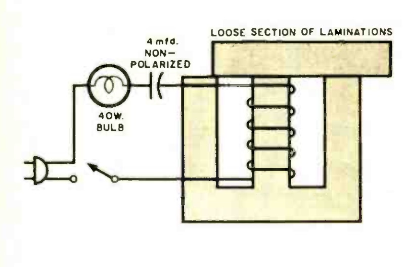
The heart of this experiment is an old choke of more than 1 Henry, capable of handling at least 50 mA. I’m guessing that one could use an old power transformer. Remove the frame to reveal the “E” shaped core inside. From another old transformer, obtain a section of laminations, which will be laid on the top.

According to the magazine, “the point of adjustment is quite critical and requires a bit of patience.” The loose section starts completely on top of the “E”. With the switch on, the bulb should not light. That section is slowly moved, about 1/32 of an inch at a time, with the switch turned off after each move. At the critical point, the bulb will flash on and off at intervals of about 1 second.

Junior will thus have demonstrated that by varying the magnetic flux, he has introduced a non-linearity which causes the circuit to flash.

It should be noted that this experiment involves 120 volt electrical current, so proper precautions should be taken.
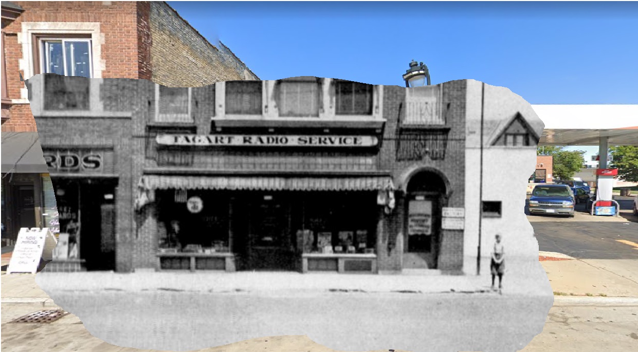
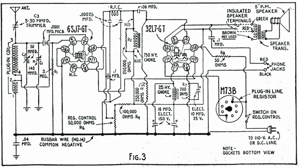


Putting Up an Aerial, 1951

1951JanBLSeventy years ago, it was a pretty good bet that a Boy Scout would have an interest in radio, so the “Hobby Corner” feature of Boys’ Life, January 1951, offered some pointers for a Scout on how to up an aerial.

The magazine noted that if you had a crystal set or a one-tube radio, then a good antenna would ensure good reception. It recommended a run of about 50-100 feet of copper wire, with glass insulators carefully placed at either end. Because the wire would contract in cold weather, some slack was called for. To avoid noise, the antenna should not be parallel to power lines, “and don’t throw antenna wire over power lines–it’s dangerous.”


1941 Two Tube Regen

1941JanPM

Eighty years ago, this couple were pulling in so many foreign stations on their two-tube receiver that they had to get out the globe to figure out where they were all coming from. They built the inexpensive set themselves by following the plans in the January 1941 issue of Popular Mechanics. Thanks to plug-in coils, the set could cover the broadcast band up to 9-1/2 meters. The set ran off household current, and could power either a loudspeaker or headphones. A 6SJ7-GT served as regenerative detector, with a 32L7-GT serving as audio amplifier and rectifier.

1941JanPM2