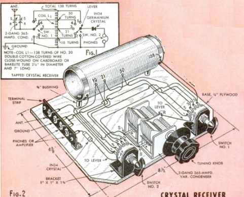
The young man shown here earned his girl’s admiring gaze by putting together two companion projects shown in the April 1948 issue of Popular Mechanics. The first was a relatively modest crystal set featuring a tapped coil, capable of pulling in the local stations with suitable antenna and ground connections.
But what really impressed her was the loudspeaker volume achieved with the audio amplifier using a 1H5GT and 1Q5GT tube to drive the 3″ speaker handsomely mounted on the front panel. The crystal set, of course, needed no power source. The amplifier ran from a 1-1/2 volt dry cell and two 45 volt batteries in series.
In addition to working well with the crystal set, the amplifier could be used with a crystal phono pickup or other electronic projects.
Ninety years ago this month, the April 1928 issue of Radio News carried this article explaining some of what happened when an SOS was heard on the airwaves.
As soon as an SOS was heard, coastal stations WNY in Brooklyn or NAH at the Brooklyn Navy Yard would immediately flash the message “QST DE NAH QRT SOS,” meaning that all stations–including broadcasters–along the Eastern Seaboard would need to immediately silence their transmitters. Network programs would continue over the wire to stations further west, but the key stations themselves would be silent. As the article pointed out, this sometimes led listeners who tuned in late to think something was wrong with their receivers. But for the radio buffs, this added some opportunities.
First of all, with all of the New York stations dark, listeners in that city had some DX opportunities. Stations such as KDKA and those further west would still be on the air.
And “broadcast listeners who are able to read the Continental Morse code and the quick flashes of radio abbreviations can often follow the rescue arrangements; for the broadly-tuned signals will penetrate into the upper reaches of the broadcast band.” The article noted that NAH used spark for these transmissions, exactly because the signal covered more bandwidth and thus had a better chance of being picked up. Similarly, under the radio regulations, the ship in distress was allowed to have its “transmitting set adjusted in such a manner as to produce a maximum of radiation irrespective of the amount of interference which may be caused.”
The receiver shown above is the creme de la creme of Soviet radio technology, the P-250, better known simply as “Кит” (kit). This receiver was produced from 1949-1980 for the Soviet Military and government, and its performance appears to rival just about anything produced in the West during that time period.
The set was originally developed for the Soviet armed forces, under the direction of Anton Antonovich Saveliev, to fill the need for a high quality receiver for use on vehicles and ships. It had a number of revisions over the years, and had the designations P-250 for the land forces, and P-670 for the navy. The receiver was a success, and the developers were awarded the Stalin Prize of the second degree in 1950.
The receiver started out strictly for official use, both by the military, as well as the KGB and GRU. The set was the apex of reliability. One example is a 1953 P-670 originally installed in a submarine, where it was used until 1970. It continued service in the coastal service until 1985, with no repairs other than scheduled maintenance.
The original 1949 version was a dual conversion superheterodyne with a tuning range of 1.5 – 25.5 MHz spread over twelve bands. A set-top box was available to extend the tuning range to 35.5 MHz. The tuning scale was customized for each receiver, with the scale printed by a photographic method. The first IF was variable from 1.5 to 3.5 MHz, with a second IF of 215 kHz. Bandwidth was switchable between 1, 3, 6, and 12 kHz. The standard power suppl6y was 127/220 volts, 50 Hz, but other supply options were available.
An improved version, the P-250M, was produced between 1957 and 1969. Among other improvements was greater precision on the tuning scale, with calibrations reduced from 2 kHz to 1 kHz.
The final version, the P-250M2, was produced from 1968 until 1980. The main change was the tube type, as the set moved from metal octal tubes to miniature tubes. A special tropical version was also available.
The set was declassified in 1959, and eventually it became sought after by Soviet amateurs. You can see the receiver in action at this video:
Yesterday, we showed this puzzle from the April-May 1968 issue of Radio TV Experimenter magazine. The question was simple enough–you had to figure out the net resistance between two opposite corners.
Fifty years ago, hobbyists encountering this problem probably started out the way I did, by scribbling the diagram on a piece of paper, trying to flatten it out, and then realizing that the standard equations for series and parallel resistors weren’t really of much help, since they were all hopelessly interlinked.
Fifty years ago, the reader had to wait two months for the answer, as shown here in the June-July issue. So I suspect that more than a few got twelve identical resistors, made them into a cube, and then measured.
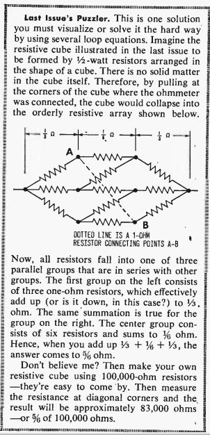
The key to solving this is to notice that the voltage reading at all three of the points marked “A” is the same. And the voltage reading at all three of the points marked “B” is the same. This is because the diagram is symmetrical, and a current flowing from the left to any of the points A is going to pass through an identical resistance. And a current flowing from the right is going to pass through an identical resistor to get to any of the points B.
Since the voltage reading is the same, we can go ahead and make a direct connection between all of the A points, and another direct connection between all of the B points. Since the voltages are the same, no current will flow, and there will be no effect on the circuit.
The effect that it will have, however, is making the problem a lot easier to solve. At this point, we have three resistors on the left, all in parallel. We have six resistors in the middle, all in parallel. And we have three resistors at the right, all in parallel. It’s easy to compute that the equivalent resistances are 1/3, 1/6, and 1/3 ohm. And those values are in series; so we just add them up, and the answer is 5/6 ohms.
This video takes a slightly different approach to arrive at the same answer:
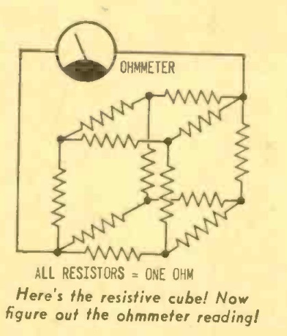
Today we offer a deceptively simple looking puzzle, taken from the April-May 1968 issue of Radio TV Experimenter magazine.
The question is simple. This cube is made up of 1 ohm resistors on each edge. What’s the net resistance between two opposite corners? The answer will appear here tomorrow.
There was a time when phonograph needles were taken seriously, and a century ago was one of those times. This full-page color advertisement appeared in the April 1918 issue of Talking Machine World.
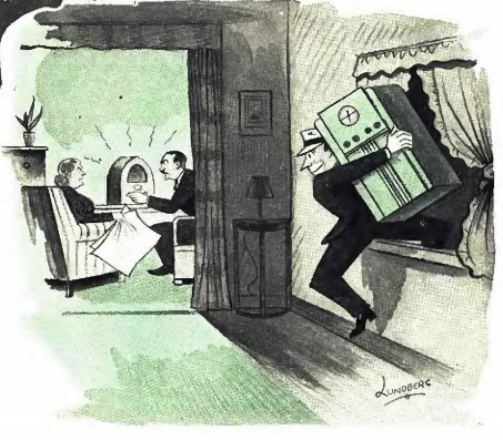
The man sneaking through the window isn’t a burglar. It’s a radio salesman trying to get a radio inside the house, where it can sell itself! The illustration appeared in the April 1938 issue of Radio Retailing in an article explaining how to sell.
The article explained that your canvassers can’t sell radios at the door, and they can’t get inside the door, because the homeowner is well aware that they’re just trying to sell. And even if they do get inside, they’re not going to sell any radios armed with photos.
So to sell radios, the canvasser needs to stop trying to sell radios. Instead, they needed to figure out a way to get a radio inside the house, where it could sell itself: “The answer is to GET THE RADIO IN THE HOUSE. And when I say get the radio in the house, I mean get the radio in the house by any lawful means at your disposal. By trickery, by cunning, by anything under the sun but a hint that you want the lady to buy it. By misrepresentation, if you will, provided you stick to your original story, even when you go back to sell.”
The article even advised having the boss go back to close the sale, rather than having the original salesman. After all, the original salesman will go to great lengths to stick to his story that he’s not trying to sell anything. The boss, on the other hand, has a bit greater aura of importance, and can probably close the sale.
The article speculated that if the original salesman handles both ends of the transaction, then he’ll probably place 100 radios and sell 80 of them. On the other hand, he could place 500, of which 250 are ultimately sold. The smart dealer figured out which system was better.
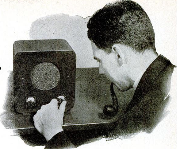
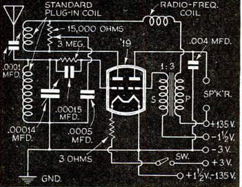
Eighty years ago this month, the April 1938 issue of Popular Science carried the plans for two interesting one tube receivers, the first of which is shown above. This set was billed as being ideal for an auxiliary set in the kitchen, den, or child’s playroom, and would give good loudspeaker reception on local stations with an efficient antenna.
While the article pointed out that it might not have been the first ever one tube loudspeaker set, it was “perhaps the first time that those results have been achieved without incorporating complicated and tricky hook-ups in the design.”
The set accomplished this by using a new dual tube that had been on the market for a few months, the type 19. The circuit used half of the dual triode as a regenerative detector, with the other half amplifying the audio enough to drive the speaker. The set was built in a homemade wooden cabinet.
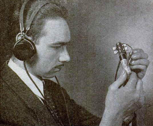
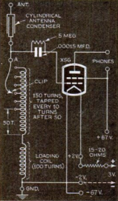
The other set featured in the magazine was more of a novelty, a vest pocket set about the size of a pocket flashlight, shown above. This one-tube set was said to give excellent earphone volume on stations within 75 miles, allowing it to be a handy radio companion for the hiker or cyclist. The filaments were powered by flashlight batteries, with a small 45 volt battery supplying the B+. It used a type XSG “ultra-midget” tube nestled carefully inside the fountain pen case.
Radio batteries had become almost impossible to find 75 years ago.
This posed a particular problem for farm listeners, many of whom relied on battery sets for weather and farm news, in addition to entertainment. The March 29, 1943, issue of Broadcasting magazine carries an article by the news director of WMT Radio in Cedar Rapids, Iowa, who wrote that many of his station’s listeners no longer had this vital link to the outside world, since their batteries had gone dead. According to the War Production Board, before the war, 4.5 million batteries were produced annually for the nation’s 2.2 million battery sets. But production had dropped to just 2.4 million batteries, for an estimated 3.2 million sets in rural homes. WPB was working on adjusting quotas, but for the time being, many battery radios were silent.
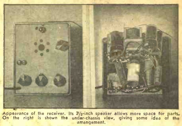
For those with electric current, the battery radio was a luxury that had to be put on the shelf for the war years. The April 1943 issue of Radio Craft carried two projects which were relevant. First of all, for those who wanted a portable radio, albeit one that could be used only where household power was available, it carried the plans for the small portable radio shown above. With batteries unavailable, and many tube types also unavailable, this set was designed with parts availability in mind.
The simple circuit used a 12SL7GT as a regenerative detector, with a 70L7GT as audio amplifier and rectifier. With a 15 foot antenna, the set would pull in local stations as well as strong stations 50-100 miles away.
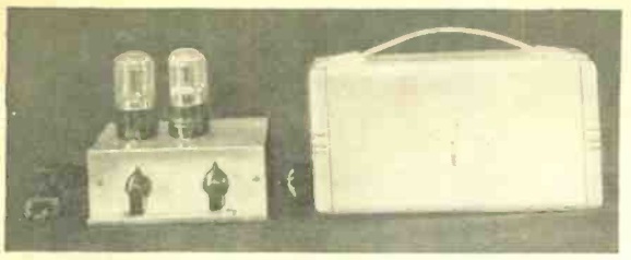
The other project, shown here, was for those who had a battery portable sitting on the shelf. This power supply would allow it to be put back in service. It used two two 50Y6GT rectifiers to rectify directly from the AC line. Dropping resistors were used on the output to provide either 67.5 or 45 volts to replace the B batery, as well as filament voltage to replace the A battery. The completed power supply is shown above next to the author’s Crosley model 45-BV “Commuter” portable.
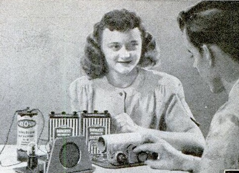 The young man shown here earned his girl’s admiring gaze by putting together two companion projects shown in the April 1948 issue of Popular Mechanics. The first was a relatively modest crystal set featuring a tapped coil, capable of pulling in the local stations with suitable antenna and ground connections.
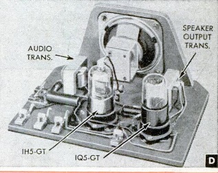 But what really impressed her was the loudspeaker volume achieved with the audio amplifier using a 1H5GT and 1Q5GT tube to drive the 3″ speaker handsomely mounted on the front panel. The crystal set, of course, needed no power source. The amplifier ran from a 1-1/2 volt dry cell and two 45 volt batteries in series.