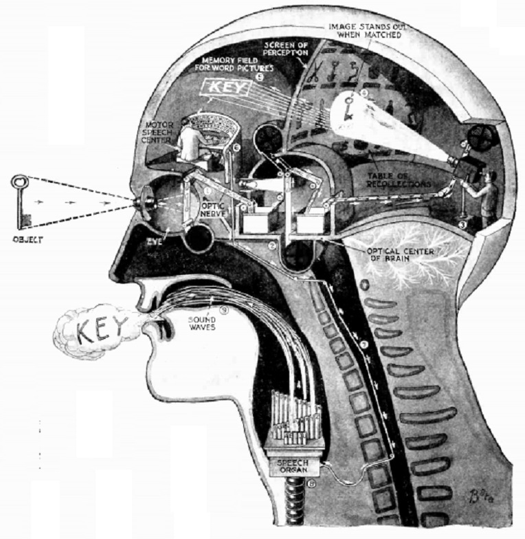
This simple self-explanatory diagram shows exactly how the brain works. It appeared in Science and Invention magazine, June 1926.
Click Here For Today’s Ripley’s Believe It Or Not Cartoon

This simple self-explanatory diagram shows exactly how the brain works. It appeared in Science and Invention magazine, June 1926.
Click Here For Today’s Ripley’s Believe It Or Not Cartoon
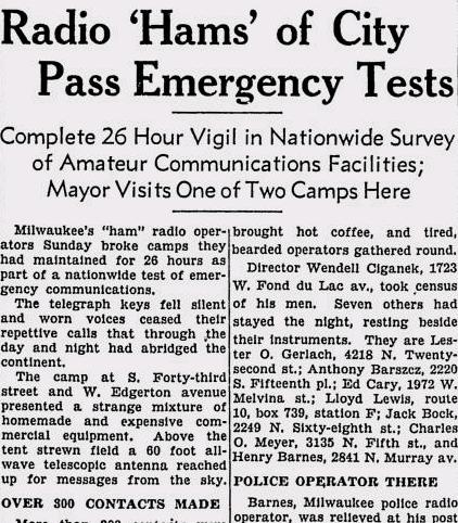
Seventy-five years ago, this day’s issue of the Milwaukee Sentinel, June 9, 1941, carried this report of ARRL Field Day, which had just concluded.
The Milwaukee hams had operated for 26 hours from a location at 43rd Street and West Edgerton Avenue in Milwaukee, a site which “presented a strange mixture of homemade and expensive commercial equipment. Above the tent strewn field a 60 foot all-wave telescopic antenna reached up for messages from the sky.”
The article reported that 291 contacts were made with all nine call areas. The furthest contact was with Puerto Rico. The paper noted that this was a test of emergency communications, and demonstrated how Milwaukee would reach the outside world should catastrophe wipe out power and telephone lines.
This was to be the last pre-war Field Day, with Amateur Radio operation silenced after Pearl Harbor. In 1940, the FCC had severely restricted portable operation, restricting it to weekends, only with self-powered apparatus intended for emergency use. 48 hour advance notice was also required. At the ARRL’s request, the FCC relaxed these requirements in a March 11, 1941 order:
It Is Ordered, That during the period of the American Radio Relay League Field Day test from 4:00 P.M. E.S.T., June 7, 1941, to 6:00 P.M. E.S.T., June 8, 1941, the prohibition contained in Commission Order No. 73 shall not apply to communications transmitted by licensed portable and portable-mobile stations participating in such tests.
The announcement of this order in the May 1941 issue cautioned that the relaxation applied only to stations participating in Field Day.
Results were published in the January 1941 issue of QST, and noted that at least 2180 individuals had participated from 163 club stations and 119 non-club stations. The Milwaukee group’s showing was overshadowed by the Tri-County Radio Association of Plainfield, NJ, W2GW/2, with 1112 contacts. That club’s contacts were evenly split between CW and phone. They had 163 worked on 160 meters, 447 on 80 meters, 245 on 40 meters, 32 on 10 meters, 20 on 5 meters, and 61 on 2-1/2 meters.
Like most Amateur Radio traditions, Field Day resumed after the war. This year’s running will take place on June 25-26. The event has continued to grow over the years. In the 2015 running, the high scorer, Potomic Valley Radio Club and Columbia Amateur Radio Association, W3AO, logged a total of 9700 contacts from 18 transmitters.
Click Here For Today’s Ripley’s Believe It Or Not Cartoon
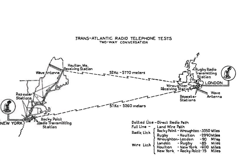
Most hams think of single sideband (SSB) voice as being a relatively modern development. It became the prominent voice mode in the 1960’s and 1970’s. But it actually dates back much earlier than that, and was in use 90 years ago, as shown in the June 1926 issue of Radio Broadcast magazine. The article describes the transatlantic radiotelephone circuit between New York and London, operating on 52 and 57 kHz.
Despite the low frequency, the circuit had reliability of about 95%. The amazing reliability of this longwave circuit is explained by two factors. First of all, brute force power was available when needed. During the nighttime hours, much lower power could be used, but the transmitters were capable of up to 150,000 watts. And to maximize efficiency, the circuit used single sideband.
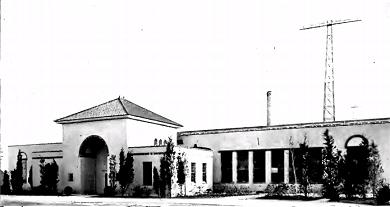
Transmitting station at Rocky Point, Long Island.
On the American side, the transmitter was located at Rocky Point, New York, and the receiving station was at Houlton, Maine. In England, the transmitter was at Rugby, and the receiver was at Wroughton, both near London. The telephone audio was initially modulated onto a 30 kHz carrier, resulting in an AM signal on that frequency. A filter was used to remove the carrier and upper sideband, and that signal was then mixed with a carrier of 90 kHz. This resulted in two SSB signals, at approximately 120 kHz and 60 kHz, as d to suppress the 90 and 120 kHz signal, leaving only the SSB voice signal on 6well as the 90 kHz carrier. Another set of filters were use0 kHz. This signal went through as many stages of linear amplification as necessary, to produce 750, 15,000, or 150,000 watts. At the receiver, a BFO carrier was introduced, making the signal audible once again.
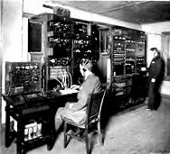
Receiving station at Houlton, Maine.
The article conceded that the system had not yet reached full commercial usefulness:
For ordinary messages of greeting, the apparatus of to-day is adequate, when conditions are favorable, but the commercial possibilities of transatlantic telephony will not be fully realized until the system is perfected to a degree that it can be used without flaw for business, news, and official conversations. This requires an adequate degree of secrecy, adding still further complications.
Click Here For Today’s Ripley’s Believe It Or Not Cartoon
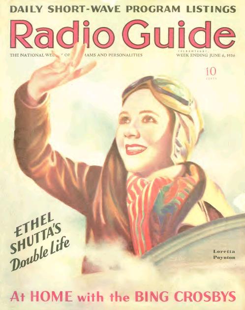
Shown here on the cover of Radio Guide, June 6, 1936, is Chicago-based NBC radio actress Loretta Poynton Carroll, who performed under her maiden name. She originally planned for a career in legitimate theater, after her intense activity in school dramatics. However, because her mother was ill, she decided to look for work closer to home, and was hired by NBC. According to Radio Guide, she played the character Ruth Morrow in “Flying Time,” and the daughter in “Don Harding’s Wife.” She was later a regular on “Amos ‘N” Andy.”
She retired from Radio in the 1940’s, and died in 1992 at the age of 77 in Thiensville, Wisconsin, according to her obituary in the Chicago Tribune.
Click Here For Today’s Ripley’s Believe It Or Not Cartoon
 June 4, 2016 was American Hiking Society’s National Trails Day®. Since many trails are units of the National Park Service, they are taking part in National Parks On The Air (NPOTA), an event in which amateur radio operators set up portable stations at National Park units and make contact with other amateurs at home. The event has been very popular, and there have been hundreds of thousands of contacts made from the parks. The North Country National Scenic Trail qualifies as a “National Park,” allowing me to operate from one of the Minnesota state parks crossed by the trail. The North Country Trail extends from eastern New York to North Dakota. As the trail passes through Minnesota, it becomes the Superior Hiking Trail, which runs from Jay Cooke State Park along the north shore of Lake Superior to Grand Portage.
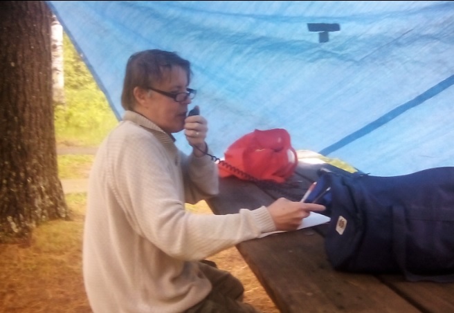
On National Trails Day, a group of hams put together an event called Light Up The Trail in which stations were set up at various locations in all of the states along the North Country Trail. As I did a couple of weeks ago, I operated from Jay Cooke State Park in Minnesota, about 25 miles south of Duluth.
The weather wasn’t quite as cooperative as it had been with my previous activation, since there was a light rain when my son and I arrived at the park. Undaunted, we moved a picnic table close to two trees what would serve as a support for a tarp. I used my trusty golf ball retriever as a tent pole on one corner, and secured the other corner to the table itself. A few taut line hitches had the protective shelter up in a few minutes, and I was ready to get on the air. My original plan was to set up dipoles for 40 and 20 meters, but with the rain coming down, I decided to stick to 20 meters only, since the total antenna length was only 32 feet. I used an inverted vee with the center supported by the golf ball retriever, and the ends tied to a tree and another picnic table. The radio consisted of my Yaesu FT-817, powered by a 12 volt sealed lead acid fish finder battery,

Old fort at Crown Point, New York, the eastern terminus of the North Country Trail, and my first contact. Wikipedia photo.
The activation was shorter than I had planned, but I managed 16 contacts in less than an hour of operating. My very first contact was with N1NDN who came back to my voice CQ from the eastern end of the trail at Crown Point State Park on Lake Champlain, New York. He had a very good signal, and didn’t seem to have any trouble copying my 5 watt signal. I also made contacts with two other parks, W3OK at Delaware Water Gap National Recreation Area, and W5NO at Gulf Islands National Seashore.
My last contact was with AA0AW, who was operating from the North Country Trail in Duluth. After packing up, we made a short stop at their location for an “eyeball QSO.” A group of Duluth hams had a large multi-operator operation, and had worked about 150 contacts by the time we stopped by.

Swinging Bridge prior to 2012 flood. Wikipedia photo.
The site from which I was operating, Jay Cooke State Park, lies next to a rapids of the St. Louis River. Because the rapids is impassible by canoe, it was the location of a portage used by both Native Americans and European fur traders, and remained in use until the 1870’s when a railroad was built in the area. The portage was an important link between the Great Lakes and the Mississippi River. From the portage, travelers could navigate the river to Savannah Portage, a six-mile link to the Mississippi watershed. Jay Cooke park was formed in 1915 and remained largely undeveloped until the 1930’s when the Civilian Conservation Corps built a number of structures. I was right next to two of these. The most iconic structure in the park is the Swinging Bridge, a pedestrian bridge crossing the river. A

St. Louis River, just upstream from the park. Wikipedia photo.
rickety version was in place as early as 1924 (a picture is available at this site), until 1933 when the more substantial suspension bridge was built by the CCC. That bridge endured until a massive flood in 2012, but the bridge has since been rebuilt to its 1930’s specifications.

River Inn Visitor Center, Jay Cooke State Park. Wikipedia photo.
My operating location was right behind the River Inn, a picnic shelter and small museum, also built by the CCC. I toyed with the idea of operating from inside the building, which had a roaring fire going in its fireplace. But unfortunately, there was no convenient way to get my antenna cable outside, so I decided to go with my expedient blue tarp.

Back of the River Inn from my operating location. The golf ball retriever is visible holding up the tarp and antenna.
The 2012 flood which destroyed the bridge continues to have an impact. Minnesota Highway 210, which serves as the access to the park (and has the distinction of being a Minnesota state highway running through a small section of Wisconsin) is still closed east of the park. The $21.3 million reconstruction of the highway is scheduled to be completed in October 2016.
Here’s some raw video shot by my son, which will give you an idea of my operating location:
Click Here For Today’s Ripley’s Believe It Or Not Cartoon
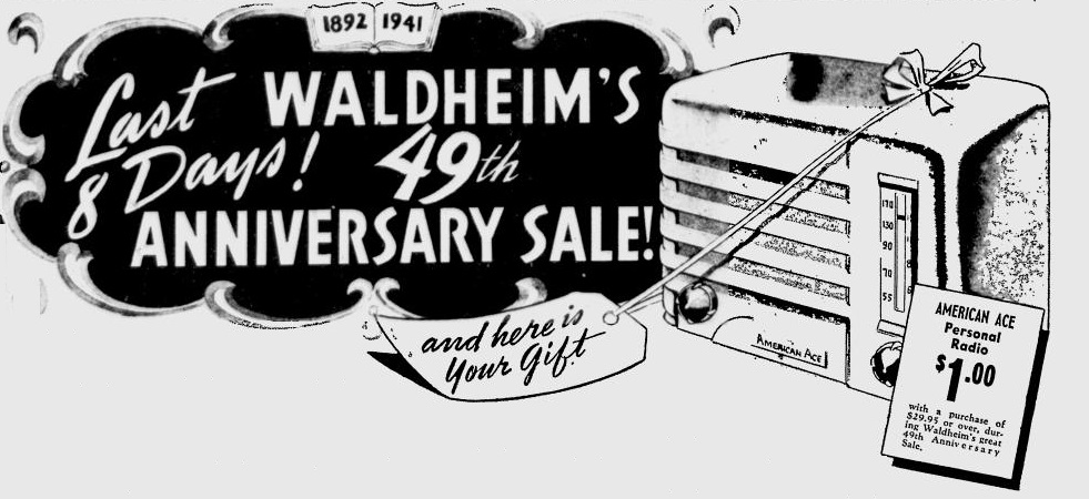
Seventy-five years ago, this little radio would set you back exactly one dollar (along with an additional $29.95 purchase) at Wadlheim’s furniture store in Milwaukee. This ad appeared in the Milwaukee Journal, June 5, 1941.
It looks like a great bargain, and it probably was being sold below cost, but this radio is about as basic as they get. While most table radios of the day were four or five tube superhets, this one was actually a two tube TRF receiver. It would probably pull in the local stations, but even then, an external antenna would probably help it along considerably. You can see a nice example of this patriotic little set at the Radio Attic, with more discussion at this forum. As can be seen at those links, the white set has red and blue knobs for the full patriotic effect.
The set is identical to the Emerson model CF-255 “Emersonette” from 1939, and uses a 12B8GT serving as RF amplifier and detector, with a 32L7GT audio amplifier. The 32L7GT also contains the rectifier. The filament voltage is courtesy of a curtain burner line cord, in addition to another fixed resistor in series.
Click Here For Today’s Ripley’s Believe It Or Not Cartoon
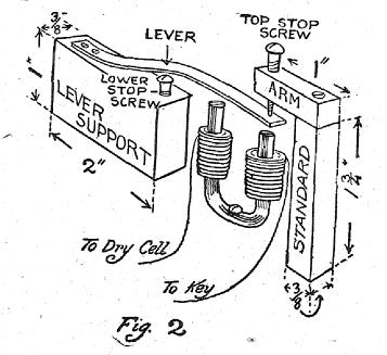 A hundred years ago this month, the June 1916 issue of Boys’ Life showed Scouts how to make this telegraph set. The plans are pretty self-explanatory. Closing the key energizes the electromagnet and makes the sounder sound. The article notes that it works just like a regular set used by the railroad and telegraph companies. It concedes that the set “isn’t much to look at, but it is a better one than Edison made when he was a beginner.”
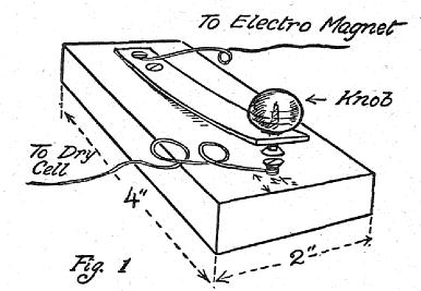
It went on to show the hookup for two sets (simply using three wires) to communicate with a friend “across the street, down the block, or over the way.”

Collins in 1910. Wikipedia photo.
The author of the article was A. Frederick Collins, a prolific early radio author of books such as the 1915 The Book of Wireless. He was also the principal author of the 1922 Radio Amateur’s Handbook.
The 1915 Book of Wireless, as well as his contributions to Boys’ Life, came on the heels of the low point in his life, a 1913 conviction for mail fraud, arising out of exaggerated claims over a wireless telephone stock promotion. In 1917, the year after this upbeat Boys’ Life article, his wife filed for separation, stating that he “had come back to freedom… with his disposition ruined”, “soured against the world, soured against even his benefactors, and soured against her,” and engaging in “long harangues and tirades of invectives against the world in general and the United States government in particular.” Collins died in 1952 at the age of 82.
Click Here For Today’s Ripley’s Believe It Or Not Cartoon
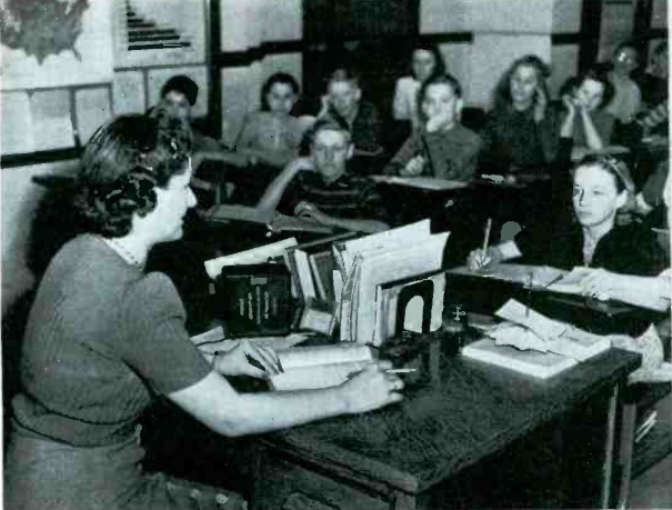
Shown here is Mary Ellen Lydon, a teacher at Monroe Junior High School in Mason City, Iowa, instructing her class 75 years ago. In addition to teaching the students in the classroom, you will notice an intercom sitting on her desk. With this device, she was able to bring instruction to shut-in students at home, as described in the June 1941 issue of Service magazine.
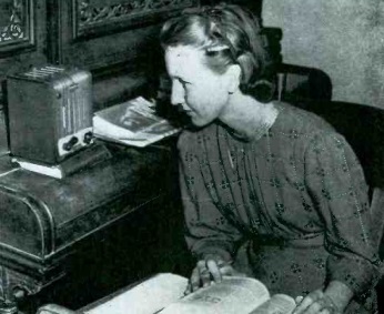
Mason City student Mary Brown receiving her instruction at home.
The article reported on the experiences of fifteen rural Iowa school districts which, mindful of their responsibility to furnish education to physically handicapped children, relied upon this method. The program began in Newton, Iowa, in 1939, when the school was unable to provide teaching facilities to a disabled student. The experiment proved a success. In particular, there was such a benefit to her morale and physical condition that she was able to return to school before the end of the semester, despite an earlier prognosis that she would be disabled for an entire year. In many cases, the shut-in students excelled academically, and in one cases, the shut-in was elected class president. In total, over a hundred sets were in use in Iowa classrooms.
The equipment consisted of standard commerical intercoms, along with transformers to allow their use over standard leased telephone lines. At school, as the students went from class to class, the intercom was brought to the next teacher’s room to allow the student to attend the full schedule of classes. The cost of equipment was about $40 per pupil served, and the phone lines were leased at a monthly rate of $1.25 for the first quarter mile, and 75 cents per each additional quarter mile. The longest distance served was about five miles.
Click Here For Today’s Ripley’s Believe It Or Not Cartoon
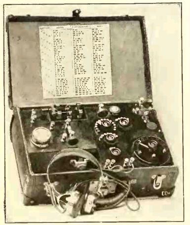
A hundred years ago this month, the June 1916 issue of Electrical Experimenter magazine carried the plans for this portable wireless set. The author noted that now that summer was in sight, the progressive radio amateur was making ready for experiments with portable equipment. However, it noted that too many sets were made of extra or discarded equipment, with disappointing results.
The set shown here promised good results with an antenna of 150-200 feet, 30 feet high on each end. The receiver was a crystal set with no power needed, and the transmitter would provide many hours of service with six internal flashlight batteries of 4.5 volts each, wired in parallel. Provision was made for six external large dry cells in series. With this power source, the set would produce a 1/32 inch spark. A test buzzer for setting the detector was separately powered with a 1.5 volt dry cell.
The author noted that the receiver pulled in NAA in Arlington, Virginia, in New York City, a distance of 275 miles, and that longer distances could be covered. The transmitter was capable of getting out about two miles, or even five or ten if an audion detector was used at the other end.
The total weight of the set, mounted in a suitcase, was about 14 pounds, and the total cost was about $15. The article notes that this cost was low enough to bring it within the reach of every wireless club or Boy Scout troop.
The author of the article was Milton B. Sleeper (1896-1963), who later went on to publish a number of magazines, such as High Fidelity and FM/TV. About the time of this article, Sleeper was working for Lee De Forest, and he later became a close associate of Major Edwin Armstrong.
The full schematic of the set is shown below, although it contains one perplexing omission.
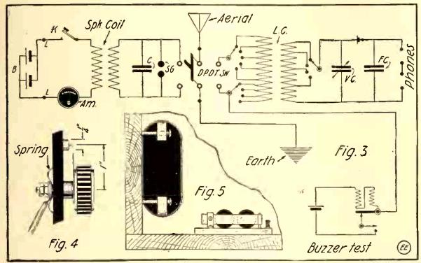
My first reaction when looking at the schematic of the transmitter was to wonder what made the coil spark, since the primary is connected only to DC, meaning that other than the instant when the key was depressed, there would be no voltage on the secondary. The article, however, mentions the spark coil’s vibrator, which is not shown in the schematic. The primary would have an series with it an interrupter, which would rapidly turn the coil on and off, resulting in a square-wave AC current, which would make the transformer work, resulting in a higher voltage on the secondary, sufficient to create a spark. Since a manufactured spark coil was used, the schematic doesn’t show this detail.
A more complete diagram of a similar transmitter, from a 1920 issue of Electronics World shows the internal wiring of the spark coil:
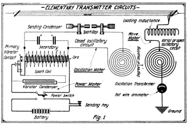
When the key is pressed, the power from the battery energizes the primary of the spark coil. In so doing, the magnetic field pulls open the primary vibrator contact, which kills the power to the primary. With the magnetic field gone, the vibrator contact closes, once again energizing the coil. The wiring is exactly the same as an electrical bell or buzzer, which operates on the same principle. This causes the primary of the coil to repeatedly turn on and off, generating a square wave, which induces a larger voltage in the secondary winding, and that voltage is large enough to generate a spark.
Click Here For Today’s Ripley’s Believe It Or Not Cartoon
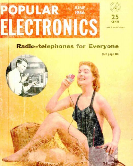
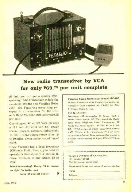
Sixty years ago, the familiar Class D Citizens Band at 27 MHz was still a couple of years away. Class B Citizens Band on 465 MHz had been authorized for a number of years, but as the June 1956 issue of Popular Electronics pointed out, the service hadn’t gained traction due to equipment requirements:
Equipment for the Citizens band (radio -telephone) must meet specifications set forth by the Federal Communications Commission. To pass these specifications, the equipment must be examined and ap- proved by the FCC in its laboratories. Because of this cumbersome arrange- ment (although fully justified), the design of Citizens radio equipment has for a number of years taken a back seat. The ice has been broken by the Vocaline Model JRC-400 transceiver, which brings Citizens band communication facilities within the reach of everyone’s pocket. After a manufacturer secures FCC approval, he may then produce identical units on an assembly line basis.
The magazine promised further reviews in upcoming issues, but included some observations about the Vocaline unit, which could operate on either 117 volts AC or 6 volts DC. The magazine’s field test showed 100% reliable ranges of 1.5 miles in a metropolitan area or 3 miles in open areas. Out in the country, weak signals were fully readable up to six miles.
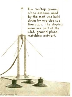 The same issue of the magazine carried this ad for the transceiver, showing its retail price of $69.75. The antenna was available separately, and consisted of a quarter-wave ground plane which could be affixed to a vehicle’s roof with large suction cups.
A schematic of the set is available online and reveals that the set used three tubes. A 6AF4 served as superegenerative detector and the oscillator for the transmitter. For audio on both transmit and receive, a 6AV6 and 6AS5 were used. The power supply included a vibrator for DC operation, and included a selenium rectifier.
Click Here For Today’s Ripley’s Believe It Or Not Cartoon