Category Archives: Telephone history

Santa Catalina Radiotelephone, 1921

1921MarRadioNews1A hundred years ago, if you were located 26 miles across the sea (40 kilometers, for those in leaky old boats) at Avalon, Santa Catalina Island, California, you could enjoy the luxury of telephone service with any telephone in the United States, thanks to the radiotelephone service operated by Pacific Telefone and Telegraph Co., as described in the March 1921 issue of Radio News.

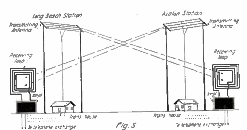
The system consisted of stations KUVX at Avalon and KUXT at Long Beach. A complicating factor was the presence of naval station NZL, also located at Avalon. To avoid interference, the radiotelephone receiving station employed a wave trap to null out NZL’s frequency. The article gives the radiotelephone wavelength of 425 meters (706 kHz). The system was full duplex, meaning that there would be different transmitting and receiving frequencies. Since the 425 meter wavelength is discussed in conjunction with the wave trap on the receiving antenna, it appears that the Long Beach station transmitted on 425 meters, and Avalon transmitted on a different frequency.

The author described an interesting catch for an SWL as part of a test conducted by the Avalon station. He listened in on a conversation from Avalon to the mainland, which was carried by the transcontinental telephone lines to New York, where the call was carried by another radiotelephone station to a ship in the Atlantic. The author reported that the voice was a little distorted, but could be clearly heard throughout the ten minute test.

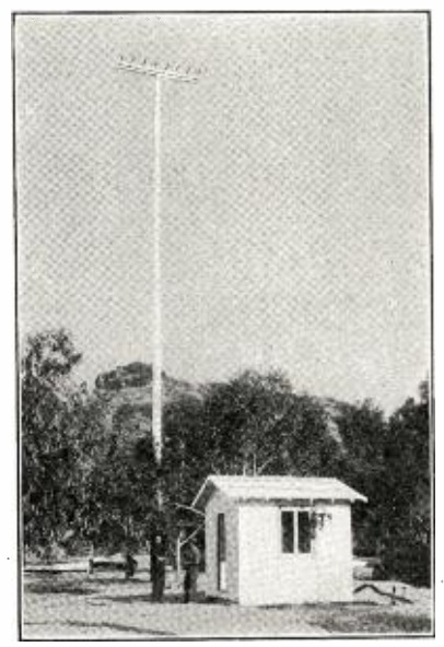
The Avalon station was powered by a motor generator, and to avoid having to restart the power, the carrier was left on 14 hours a day, with calls to and from local hotels, stores, and residents carried as needed. A licensed radio operator oversaw the transmitter, connected to an eight-wire antenna, and receiver, connected to a loop antenna. A telephone operator put through the calls, presumably with another operator at the Long Beach side of the circuit doing the same.

The system was able to transmit telegraph signals simultaneously with telephone conversations without interference. This was accomplished by “superimposing a high pitched harmonic on the carrier wave.”

A more detailed technical description of the system can be found in the December 1921 Proceedings of the IEEE.  You can also find additional references at Wikipedia, which notes that the system was replaced by a submarine cable in 1923, ending the possibility of radio listeners being able to tune in to telephone conversations.

1921MarRadioNews2


1960 Telephone Amplifier

1960DecPMSixty years ago this month, this stenographer dutifully takes down a verbatim transcript of her boss’s telephone conversation, thanks to a Lafayette telephone amplifier. The amp is connected to the phone through a telephone pickup coil, still readily available today. With it plugged into the amp, she can easily hear both sides of the conversation.

The unit was actually a kit. While it is not specified, we suspect that the secretary put it together herself, since it freed her of the need to use a headphone for such tasks, and probably made her work much easier.

The photo appeared in the December 1960 issue of Popular Mechanics, which highlighted a number of available kits, and pointed out how many, such as this one, could make things run more smoothly at the office.


Laying Telephone Wire by Airplane

1945SepPMIt looks like Bell Labs was working on this idea toward the end of the war, and it probably wasn’t implemented, at least on a very large scale. But this ad from the September 1945 issue of Popular Mechanics sounds like a good idea for quickly laying lines for military field telephones. Instead of having men do the work on the ground, possibly through enemy territory, an airplane does the job, at a rate of 16 miles in 6 – 2/3 minutes. One end, with a weight and parachute, is dropped to the ground. Then, wire is spooled out continuously.


1920’s Answer to the Zoom Worship Service

1920ElecExp1With most of the world locked down due to the threat of COVID-19, places of worship have been scrambling to deliver the Word of God to the faithful at home. But long before Zoom and YouTube were a thing, churches have relied upon technology to connect with members, as shown by this illustration from a hundred years ago this month, in the May 1920 issue of Electrical Experimenter.

Zion English Baptist Church, Penycae - geograph.org.uk - 729952.jpg

Zion English Baptist Church, Pen-y-cae, Wales, the likely origin of the 1920 transmissions.  Wikipedia photo.

Shown here is miner Sam Pritchard of Penycas, Ruabon, Wales. In 1919, he was injured by the fall of a rock. Undaunted, he was able to hear the service at the Baptist Church thanks to a telephone rigged by three of his friends.

A button microphone and batteries were strategically placed near the pulpit, with wires run to Mr. Pritchard’s bedside some distance away. A telephone receiver was strapped to his head, through which he was able to take part in the service. The magazine noted that the apparatus required was not expensive, and that such a setup could prove valuable in the northern or western United States where deep snows often cover the country.

Of course, over the years, churches have moved on to radio, then audio recordings, then television, and then the internet to deliver their message to those shut in at home. Incidentally, the OneTubeRadio Laboratories are currently hard at work preparing a 100 mW AM transmitter which will operate, with a 9 foot antenna, to broadcast church services within a parking lot. The internet works well for those who are at home, but everyone signal is slightly out of synch with everyone esle. At such time as it becomes possible to congregate a bit more closely, in parked cars, radio will allow everyone be able to listen simultaneously (or as simultaneously as the speed of light allows).  We have verified that the transmitter is up to the task, and today, we received the parts necessary to provide a high-fidelity audio feed.  We’ll post updates as the project is completed.


1920 Robbins Telephone

1920AprilBLA hundred years ago, the Scout or “any Real Boy” desiring to set up his own private telephone exchange couldn’t go wrong with these telephone sets from the Robbins Manufacturing Company, 1807 North Central Park Avenue, Chicago. For $2, the company would supply two transmitters, two receivers, and a hundred feet of wire. The sets would work over a much longer distance with ordinary bell wire.

For Real Boys desiring a deluxe setup, two wall phones (suitable for grown ups, too) and 300 feet of wire were available for only $6.

The ad ran a hundred years ago this month in the April 1920 issue of Boys’ Life.


1935 Light Beam Communicator

1935MarPM85 years ago this month, the March 1935 issue Popular Mechanics showed how to make this light communicator, said to have a range of about a half mile.

The receiver used a caesium photo cell, which the magazine said could be had for about $3. This was fed into a two-tube amplifier which could drive a speaker or headphone.

For audio amplification at the transmitter end, the system used the household radio receiver, and the magazine explained how to hook up the microphone. The the light beam generator used a system I’ve never seen before. Instead of electrically modulating the light bulb, a mechanical approach was used. The speaker was disconnected and the output was instead connected to a magnetic headphone that had been modified. The outer cap of the headphone was unscrewed and cut so that most of the metal diaphragm was visible. Then, the “diaphragm is slipped off and taken to any plating firm to be finished in the same manner as an audio headlight reflector.” The headphone was reassembled, and the result was a mirror that would vibrate in time with the sound. An auto headlamp was used to illuminate the mirror, and this was focused through a lens with a focal length of about 12 inches.

The result would have been a narrow beam of light that was modulated. At the receiving end, another lens was used to focus the beam on the photo cell.

For a unique science fair project, the advanced student could adapt this project using modern materials.  When I was a kid, I built a similar system using a flashlight as the transmitter.  The bulb was wired in series with the secondary of an audio transformer.  The primary was fed by the output of an amplifier.

For the receiver, I used a solar cell fed directly to the input of an audio amplifier.

1935MarPM2


1920 Telephone Set

1920JanBLA hundred years ago this month, the January 1920 issue of Boys’ Life magazine carried this ad for a real telephone for real boys. The set came with two transmitters, two receivers, and 150 feet of wire, all for $2. The ad noted that for longer distances, bell wire could be used. The set was available from dealers, or directly from the Robbins Manufacturing Company, 1807 N. Central Park Avenue, Chicago. It was billed as just the thing for scout work.


Avoiding Telephone Annoyance, 1920

1920Jan19EveningLedgerFor those who are annoyed by noise while talking on the phone, then this device from a century ago would prove helpful. As shown, the earpiece covers both ears, ensuring that your call won’t be interrupted.

The picture appeared in the Philadelphia Evening Public Ledger a hundred years ago today, January 19, 1920.


1919 Forest Service Heliograph

1919NovElecExpOne hundred years ago, the forest ranger shown here is acting as “lookout man” atop some Western peak. As he watches for forest fires, he has at his disposal detailed maps of the area, as well as two means of communication. When he spots a fire, he can call in the bearing to headquarters on the telephone. To communicate with other spotters in areas too remote for a phone, he has the heliograph. On clear sunny days, the device had a range of up to 45 miles.

The first Forest Service heliograph units had originated with the Army Signal Corps, but more compact units suited to forest fire fighting were procured. Seven rangers were initially trained. Even though they had no prior knowledge, they became proficient operators in a very short time.

While Morse Code could be used, it was found that the Myer Code, shown below, was more reliable for visual signaling. The letter P, for example, is 1211. The one indicates a long flash, and the 2 indicates two short flashes.

MyerCode

The top photo appeared in the November 1919 issue of Electrical Experimenter. More details of the system can be found in a 1914 Forest Service Publication, Systematic Fire Protection in the California Forests.  The heliograph instrument consisted of a mirror, which was oriented so that it reflected the sun on the receiving station. A shutter in front of the mirror was used to key the beam on and off. To call another station, the sending station would send a quick succession of flashes until acknowledged. Then, each station would turn on a steady flash to make adjustments. When the mirrors were in place, the sending station would proceed with its message. The average speed of transmission was found to be about four words per minute.

Plans for a simple heliograph can be found at an earlier post.


1959 Radio/Intercom

1959RadioTVExp3Sixty years ago, the occasional publication Radio-TV Experimenter carried this interesting project. As the enclosure, it used an already antique crank-type wall telephone as the housing for a radio receiver, but put the telephone back into service as a home intercom.

According to the magazine, the phone was rapidly vanishing from the American scene, and interior decorators had been busy snatching them up to convert into spice cabinets, pin-up lamps, and liqueur chests. Instead, the magazine showed how to preserve the original communication function by providing an intercom between floors of a house, between house and garage, etc.

The radio function was added by use of something found in almost every home, “a small table-model radio set of the ac-dc type that has been set aside because of a broken cabinet, missing knob, or a minor circuit defect.” Such a radio was squeezed in, with the controls mounted under the phone’s writing desk.

Obtaining the phone was a matter of ordering one from Telephone Repair & Supply Co. of 1760 W. Lunt Ave., Chicago, where it was available for $7 plus postage for the 20 pound instrument. Most such surplus phones came with the crank, but not the magneto, since apparently the phone companies still needed some of those for their rural customers.  The phone will have been in service for fifty years, so the article gave details on how to refinish the wood and metal components.

The article next explained how to wire the phone back up. Even without the magneto, the ringer could be made to work by including a button on the side of the phone (where the crank used to be), wired to the bell through an induction coil. Presumably, the phone would ding once when the button was depressed. A three wire circuit (or two wires plus ground) was used to hook the phones together, with one wire for the voice connection and one for the ringer. The wiring diagram is shown here:

1959RadioTVExp4