Category Archives: Science fair ideas

1945 One Tube Broadcast Set

1945NovRadioCraft
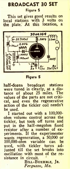
Seventy-five years ago this month, the November 1945 issue of Radio Craft carried this circuit for a simple one-tube receiver for the broadcast band. The set used either a type 30 or 1G4 tube, with as little as 3 volts B+ on the plate. The circuit had been sent in to the magazine by Bill Buehrle, Jr., of Ferguson, MO, who reported that he was able to pull in a half dozen stations clearly from 25 miles away.

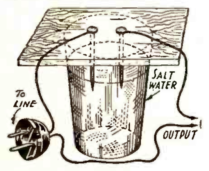
Even though the circuit was published after V-J Day, it’s likely that it was perfected while the War was still in progress with its attendant parts shortages. The author points out that parts weren’t critical. In addition to the tube and headphones, the circuit required only six manufactured parts, two resistors, two fixed capacitors, and two variable capacitors. The coils and the RF choke could be wound at home.

The circuit could be easily duplicated today. The tube is still readily available on eBay. The type 30 and the 1G4 are electrically identical, but my preference would by the 30, since its glass has the classic styling of the 1930’s era bottle, as opposed to the more “modern” octal style 1G4.   It’s such a simple set that it would form the basis for an excellent science fair project. And with only 3 volts involved, it would even be a safe project. The original article contains some suggestions on how the circuit could be modified, so comparing some of these modifications would make the project very worthwhile.  The young scientist needing to track down the parts will find some helpful leads on my crystal set parts page.


1960 Handwriting Recognition

1960NovEE3
Shown here in the November 1960 issue of Electronics Illustrated is 17-year-old Belmont Frisbee, then a student at Burroughs High School in China Lake, California. He was one of the winners of the 1960 National Science Fair and is demonstrating his winning entry here. The device he constructed is dubbed “Adicof,” and allowed the entry of numbers into a computer by writing them by hand.

The digit is written with a metal stylus onto a panel with inlaid copper strips, as shown in the diagram below. For example, when making a “2”, the stylus will pass over strips 1, 2, 3, 4, 5, and 7.

The nearly forgotten art of relay logic is used to determine which number was being written. A partial diagram is shown below. Each strip is attached to the coil of a relay. The first relay is single pole, double throw (SPDT). The next one is DPDT. The one after that is 4PDT. Unfortunately, there probably weren’t any 128PDT relays on the shelf for the seventh relay, so multiple relays were used for the higher stages.

I believe the circuit shown here is simplified in one respect: For this to work, it would be necessary to use some type of latching relay, since the stylus would no longer be in contact with the pad when the next pad is contacted.

The simplified diagram shown here uses light to indicate the digit drawn, but for his exhibit, Mr. Frisbee hooked the output to a computer.

Today, it’s a trivial matter for a computer to recognize hand input, but the concept is nothing new. Sixty years ago, a high school student accomplished the task with electromechanical relays.

Mr. Frisbee continued as an engineer after high school. He was issued at least two patents (4,477,812 and 8,009,084), both of which involve radar, and both of which list the U.S. Navy as the assignee.

The magazine highlighted some other winners of the 1960 National Science Fair. Remarkably, it includes an electron microscope constructed by Marvin Hutt, a New York high school student, despite having experts tell him that making one at home was impossible. For students looking for inspiration for a science fair project, perhaps there are a few who could build an electron microscope from scratch. But in an age when computing power is taken for granted, there’s something to be said for being able to use mechanical relays for programmable logic. The science teacher might not even realize that it’s possible, and proving the impossible is always a good way to take home the blue ribbon.

1960NovEE4


1970 Soviet Fax Machine

SovietFaxThe magazine doesn’t show all of the construction details, but if you want to be accused of Russian meddling in the science fair, here’s the project for you. For the young Soviet comrade wishing to take home the blue ribbon in the oblast science fair, the November 1970 issue of Юный техник (Young Technician) magazine gave enough information to build a fax machine. Apparently, it was called a “phototelegraph-integrator”, since that is the title shown here.

Both of the drums are spinning at exactly the same speed.  A scanner is moving across one of them, and a printing element, such as a pen, is moving across the other one, at exactly the same speed.  One of the machines scans a picture of the word Mir (peace), and this is transmitted to the printer, which makes an exact facsimile.

The bright American student can also build a device that can transmit pictures through a wire. The key is to have two drums that are spinning at exactly the same speed. The easy way to accomplish this, for demonstration purposes, is to simply have both of them revolving together on the same shaft. Both of them need to have something that moves along the drum at exactly the same speed. The easy way to do this, for demonstration purposes, is to have the sending and receiving elements connected together with a shaft.

One of those elements needs to have a method to detect the picture. In a fax machine, that’s done with light. But an easy way to do it, for demonstration purposes, is to create the image using aluminum foil. Then, the sensor can be nothing more than a piece of wire that comes into contact with the foil.

This wire is hooked to a circuit which operates a solenoid. The solenoid raises and lowers a pen which comes into contact with the other drum. Whenever the wire on the sending drum comes into contact with the foil, the circuit is closed, and the pen starts drawing on the other drum.

Turn the drum while slowly moving the two sensors. The result will be a drawing exactly the same shape as the piece of foil.

The crude drawing below shows the general idea. An advanced student should be able to work out the invariable bugs and build their own fax machine. When you take home the blue ribbon, the other students will probably accuse you of winning due to Russian meddling. When they do, point out that there was nothing in the rules prohibiting it.

FaxMachine


Science Fair Idea: Jacob’s Ladder

1960NovEE5This young woman undoubtedly took home the blue ribbon in the 1960 science fair. And she certainly earned herself considerable street cred as a mad scientist by putting together this Jacob’s ladder, by carefully following the plans in the November 1960 issue of Electronics Illustrated.

As revealed by the schematic diagram below, the circuit is simplicity itself. It simply takes normal household current and runs it into a transformer which steps it up to 12,000 volts, which is fed into two electrodes. One way or another, there is going to be an arc between the two conductors. It will follow the path of least resistance, and thus starts out at the bottom, where the two metal rods are closest together.

The arc heats the air right above it, which ionizes the air. The ionized air thus becomes the new path of least resistance, and the arc moves upward. The process repeats until it reaches the top, at which point a new arc forms at the bottom.

The critical component, of course, is the high voltage transformer. In 1960, it was available in the form of a neon light transformer, for $12 plus shipping. Of course, neon signs still exist, and you can buy the transformers on Amazon.  This modern replacement is rated at “only” 10,000 volts, but it seems like that should be sufficient.

The 1960 article includes a number of important safety features. First of all, the electrodes are safely behind a sheet of 1/32″ clear acetate. This also appears to be available on Amazon.

And the choice of switch ensures that the device isn’t turned on accidentally. The power switch is a momentary switch, meaning that when you let go of the switch, it turns off. It’s a SPDT switch, meaning that when it’s off, another contact is energized. This is wired to a green pilot light that indicates that the device is plugged in. The switch has a safety cover, meaning that one needs to consciously lift the cover to flip the switch.

The article begins by saying that “if the directions given in this article are followed to the letter, there is no danger of shock. Don’t take short-cuts or omit the built-in safety features of this model; it is poor economy to leave out relatively inexpensive components that might prevent a nasty shock.”

These days, when one reads safety warnings, there’s a tendency to ignore them. But in 1960, when a warning like this was included, it’s because the activity in question was, indeed, dangerous, and you really needed to be careful. So I believe this project is suitable for mature students, working under the supervision of a competent adult. But this contraption is potentially lethal, and great care must be taken in its construction and use.  In 2016, a Michigan teen was killed trying to build one, and we don’t want any of our readers to suffer the same fate.  So please be careful.

1960NovEE6


1940 Clock Radio

1940NovPM

The humble clock radio hit the scene shortly after the war, but as we can see from this self-explanatory drawing in the November 1940 issue of Popular Mechanics, one John L. Story of Washington, D.C., had come up with the idea. He mounted a small toggle switch on the back of a wind-up alarm clock not unlike the one shown at left, still available on Amazon.

When this type of clock rings, the key for winding the clock unwinds.  The switch is carefully placed so that the unwinding key trips it, turning on the radio or other small appliance.  For students interested in the history of technology, this would be an interesting science fair project to duplicate Story’s invention and answer the question, “what is the simplest clock radio?”


Using Dual-Filament Light Bulb as Rectifier or Detector

Converting dual-filament lamp to diode tubeWe previously featured the idea shown at left, using a dual-filament light bulb as a diode tube.  The idea is to burn out one of the filaments, and use that as the plate.  The other filament becomes a directly heated cathode.  This is from the January 1943 issue of  Radio News, which also included other ideas for emergency crystal sets.  This one called for a 6-volt type 1158 lamp, which is still available on Amazon, although the same idea could be used with a 12 volt type 1157, which is available at at Amazon or WalMart.

1920SepPSThe same idea appeared a hundred years ago this month in the September 1920 issue of Popular Science.  This one was to use the bulb as a rectifier and not detector, but the idea is the same. The idea was sent to the magazine by one R.U. Clark, 3d:

The bulbs used as rectifiers are the bayonet-base type, round automobile headlights of the double-filament type, just recently put on the market for the Ford automobile. One filament should be burned out by an over-voltage current applied to the proper terminals. The connecting wire and all that remains of this filament can then be used as the plate, and the remaining filament, which consumes only .85 amperes, can be used to supply the electron stream.

The usual alternating current can be fed to the filament and plates of these bulbs when suitably reduced by transformers, and direct current taken out in the manner usual with such devices.

These tubes will pass about 0.5 amperes each under suitable conditions.

The author notes than many want to experiment with vacuum tubes as rectifiers, but don’t want to run the risk of damaging expensive tubes. The Ford light bulbs, on the other hand, sold for only 65 cents, making such experiments more forgiving. The illustration here shows to bulbs, presumably mounted as a full-wave rectifier.

Making a homemade vacuum tube in this manner would make a very interesting science fair project.  To demonstrate, an old “wall wart” transformer could be used as the input.  Most have a DC output, but some have a low voltage AC output.  Examine the ones available at the closest thrift store, and chances are, a suitable one can be found.  By using an inexpensive multitester that measures both AC and DC voltage, it can be shown that the input is AC and the output is DC.


1940 Toy Submarine

1940AugPSIf Junior is looking for a spectacular science fair project that can be built at little expense, but still uses a slightly dangerous chemical, he can’t go wrong building this real submarine, according to plans contained in the August 1940 issue of Popular Science.

When released in the local pond, the submarine repeatedly submerges and surfaces, all the time moving forward in the water. The secret of all of this is a small amount of calcium carbide, the same chemical used in old-fashioned miner’s lamps. When the chemical is exposed to water, it generates a high pressure gas, which is used to propel the vessel and provide buoyancy. The chemical is readily available at Amazon, and probably at your friendly local hardware store.

School will eventually reopen, so your young submariners can take advantage of their summer vacation to build and test the craft, which can be made out of scraps of sheet metal and tin cans. Soldering is required, but kids naturally enjoy working with molten lead. When school reopens and the science fair is on, the submarine can be used for a variety of scientific experiments involving buoyancy, propulsion, or chemical reactions. The teacher has probably seen old movies with miners wearing headlamps, but this will probably be their first exposure to the actual chemical used. A blue ribbon is almost guaranteed.

1940AugPS2


Science Fair Project: Moving-Coil Ammeter

1970AugSciElec2
1970AugSciElec
The young man shown here is probably getting ready to collect his first Social Security check, but fifty years ago, he undoubtedly took home the blue ribbon at the 1970 Science Fair. His project was shown in the August-September 1970 issue of Science and Electronics. According to the magazine, the project would show off knowledge and understanding, but would also require dexterity with tools.

The project was a moving-coil ammeter, not unlike a commercially made meter movement. While the magazine didn’t use the moniker, this type of meter is also commonly known as a d’Arsonval meter movement, after Jacques-Arsène d’Arsonval. For less advanced students, the article referred back to construction articles for some more primitive meters, such as the hot-wire ammeter we previously profiled. Most of the meter’s mechanical parts were made of wood, so the project required some expertise in the wood shop. The form for the moving coil was made with balsa wood, whose light weight ensured a sensitive movement.

The finished product could be accurately calibrated by using a commercial VOM, a battery, and a potentiometer. Current readings were noted on the commercial meter, and then marked on the face of the homemade meter.

According to the article, if the builder used reasonable care and followed instructions, they would be assured of a good grade and congratulations from friends and teachers.  And fifty years later, there’s no reason to think the result would be any different.


Expedient Variable Resistor

1945AUgRadioCraftI’m not sure it would comply with modern OSHA rules, so whatever you do, make sure you don’t touch any of the exposed conductors. But if you need to quickly come up with a low voltage, this self-explanatory method of making your own resistor should do the trick. Measure the voltage, and keep adding salt until you get the desired voltage.

The idea appeared in the August 1945 issue of Radio Craft.  It had been sent in to the magazine by one Ollie Peoples of Mountain View, Oklahoma, who pointed out that if you can’t reach the desired voltage, then use a larger glass and add more salt.  He reported that the average glass wouldn’t deliver more than six volts, and would get unduly hot with that voltage.

As long as they’re careful with the high voltages involved, advanced students could use this idea as part of an interesting science fair project, demonstrating how changes in salinity affect the resistance.


Science Fair Idea: Magnetic Field from Static Electricity

1940JulyPS1For the young scientist who wants to outsmart the science teacher, here’s an excellent science fair project that duplicates the work of American physicist Henry Rowland.

Your teacher undoubtedly knows that a an electrical current generates a magnetic field. But what your teacher probably doesn’t know is that a moving charge of static electricity also generates a magnetic field. This can be demonstrated from this experiment in the July 1940 issue of Popular Science.

To do the experiment, you set up an electric motor as shown here. You attach a disk of hard rubber, which you electrify by rubbing it with a woolen cloth. (Instead of the rubber disk, you can use an old phonograph record. If you don’t know what that is, you can ask your grandparents, or read some of our posts about the history of the phonograph).

Once the disk is charged up, you turn on the motor. As soon as it starts spinning, a compass placed nearby will deflect, showing the presence of the magnetic field.