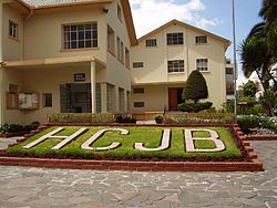
HCJB grounds. Wikipedia photo. by Mschaa – Own work. Licensed under GFDL via Wikimedia Commons.
In the early 1940’s, the physics department of the University of Chicago was undoubtedly an exciting place. In late 1942, the world’s first self-sustaining nuclear reaction took place under the stands of the football stadium under the direction of Columbia Unviersity Professor Enrico Fermi.
On Easter Sunday 1940, the atomic pile had not yet been built, but the University was clearly about to be at the center of some of the greatest science of our time. But one graduate student was about to hear a different call, and it came over the shortwave radio.
On Easter Sunday, 1940, a new radio station had just come on the air and was conducting its inaugural broadcast with a new 10 KW shortwave transmitter. The station wasn’t entirely new, but it had just installed the new transmitter, and it now had a strong signal to North America. That station was HCJB, the Voice of the Andes, in Quito, Ecuador.
The station had been founded in 1931 by American missionary Clarence W. Jones. Jones had worked under Chicago evangelist Paul Rader, who had been one of the first radio evangelists, having a weekly program called “WJBT” (Where Jesus Blesses Thousands), which was carried by WBBM in Chicago. Jones had been impressed by the radio’s ability to spread the Gospel, and felt called to establish a radio ministry in Latin America. In 1928, he traveled to Venezuela, Colombia, Panama and Cuba, seeking a location for the station, but was unable to receive government permits in any of those countries.
Later, Christian and Missionary Alliance missionaries to Ecuador encouraged him to start the radio station there. In 1930, Jones obtained the approval of the Ecuadorian government to begin a station,
HCJB came on the air on Christmas Day, 1931. The initial 30-minute broadcast in English and Spanish was from a fairly respectable 200 watt transmitter. But that transmitter was sitting on a table in Jones’ living room, with a simple wire antenna strung between two poles. And there were only six receivers in the country at the time.
Notwithstanding its small start, the station continued to grow. And by 1940, it was able to install the substantial 10 KW shortwave transmitter that would provide good coverage in both South and North America. By 1941, broadcasts were expanded to include Russian, Swedish and Quichua. Other languages soon followed.
The inauguration of the new shortwave transmitter was noted in North America. The shortwave bands reflected the fact that Europe was now at war, and the message of peace transmitted from Ecuador was a breath of fresh air. The shortwave editor of Radio Guide magazine made these observations in the April 20, 1940, issue:
“The Voice of the Andes”
To those listeners tired of the eternal babble of Europe’s shortwave voices of hate and war: Turn your dials to HCJB (12.48), “The Voice of the Andes,” at Quito, Ecuador. Here, at an elevation of 10,000 feet, encircled by eleven snow-capped peaks of the mighty Andes, nestles the oldest city of the New World, one of the ancient capitals of the Incas steeped in fifteen hundred years of traditions; a city whose many white churches shelter staggering treasures in gold and precious stones; a city with winding cobbled streets, overhanging balconies, ancient archways, sunlit plazas and countless white-stone houses perched crazily on steep hillsides, their red-tile roofs, with green moss cropping out here and there in the cracks, forming vivid splotches of color against the snowy mantle of the guardian peaks.
Such a historic and picturesque setting seems indeed a fitting site for a missionary radio station whose messages are those of peace and good-will. This new 10,000-watt modern short-wave transmitter–the most powerful in South America and the only broadcast station to employ a fully rotatable antenna–stands as a tribute to the sacrificing labors of one many–Clarence Jones, a gospel missionary from Chicago, whose lifework is to minister to and teach the Andean Indians. Because of the rugged contours of Ecuador, making transportation exceedingly difficult, Reverend Jones recognized long ago the vital value of radio in carrying on his work and subsequently installed several small short-wave stations at Quito, including the former 1,000-watt transmitter of HCJB and a mobile broadcasting station which carries this active pastor’s voice to the most remote jungle and mountain tribes. The new station–a labor of love paid for by voluntary subscriptions from his loyal friends–was built by an American amateur, Clarence Moore, who is well known to hundreds of amateur friends under his call, HC1JB. The new “Voice of the Andes” was officially inaugurated on Sunday, March 24.
On the dial, HCJB (12.46) comes in above the 25-meter band and approximately half-way between the 12 and 13 megacycles figures in frequency. You will have no trouble in hearing HCJB, since its unique location and rotatable aerial make it possible for it to project strong signals into North America.
HCJB is on the air for several hours daily with Spanish programs for the benefit of listeners in the Latin Americas, but English listeners will be primarily interested in “Ecuadorian Echoes,” on from 6:00 to 7:00 p.m., and the “Friendship Hour,” broadcast nightly except Mondays from 9:00 to 10:00 p.m. EST. These all-English programs are directed specifically to North America. “Ecuadorean Echoes,” one of the most interesting programs on the air, breathes the very soul of Latin America. During this period the native music, the literature and the very lives and habits of these romantic peoples come to life and parade before the microphone. “The Friendship Hour” is a strictly good-will program consisting of classical music, old-time hymns, simple gosple messages, the reading of letters from listeners and personal messages to friends everywhere.
Among the listeners to that first program on Easter Sunday 75 years ago was University of Chicago graduate student Clayton Howard. He had received his undergraduate degree in physics the previous year from nearby Wheaton College. He had been born in China to missionary parents who returned to the United States when Clayton was 9, in order for Clayton’s father, Charles Howard, to organize the biology department at Wheaton.
By this time, Clayton was a licensed amateur radio operator. In the 1938 call book, he is listed as holding call sign W9KJZ. For whatever reason, he happened to be tuning above the 25 meter band that night and heard the new station. He later recounted that he was aware of a missionary station in South America, but knew little about it before chancing upon its broadcast that night. He was intrigued enough to seek out Reuben Larson, one of the missionaries to Ecuador who had a decade earlier encouraged Jones to start the station.
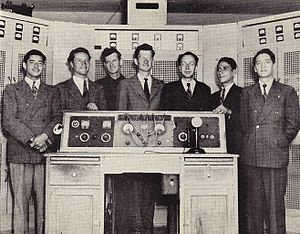
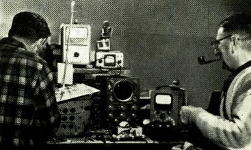
HCJB technical staff in 1945. Head engineer Clayton Howard is in the center. (Image by by SkagitRiverQueen, Licensed under CC BY-SA 3.0 via Wikipedia.)
The name Clayton Howard is familiar to many hams and shortwave listeners. 1941 saw Howard be commissioned by his church as a missionary and accept a call to serve on the technical staff of HCJB. Howard went on to become the station’s chief engineer, and is best known as being the on-air host of the “DX Partyline” program, which he produced and hosted for 22 years. This program was very popular with SWL’s, as it included station reports and other listening tips. The program always concluded with Howard offering a short segment entitled, “Tips for Real Living,” in which he shared with listeners a brief Gospel devotional message.
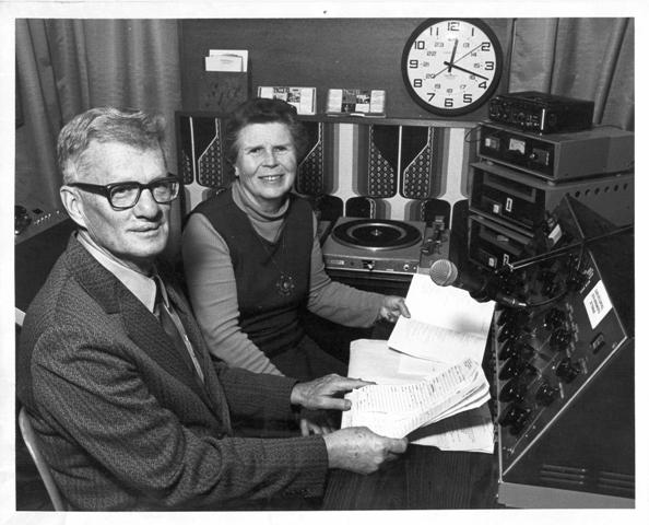
Clayton Howard and wife Helen hosting DX Party Line, 1970’s. HCJB photo.
The Soviets didn’t normally provide recognition to Christian missionaries, but in Howard’s case, they made an exception. When Howard retired in 1984 and made his last DX Partyline broadcast, Radio Moscow announced that “the living legend of the Andes has retired.”
If you grew up as I did listening to a shortwave radio in the 1960’s and 1970’s, the name Clayton Howard is certainly a familiar one. And chances are, you heard one of those tips for real living. If you did, it was probably because on Easter Sunday, 1940, a 12.48 megacycle radio signal traveled from the Andes to a receiver in Chicago.
As a result of that Radio Signal, Clayton Howard probably never met Enrico Fermi. He probably had nothing to do with the construction of the atomic pile under the football stadium. If he had, perhaps Howard would be remembered today as a nuclear physicist. But God called him elsewhere, and it appears that He made that call on 12.48 megacycles.
References
Read More at Amazon
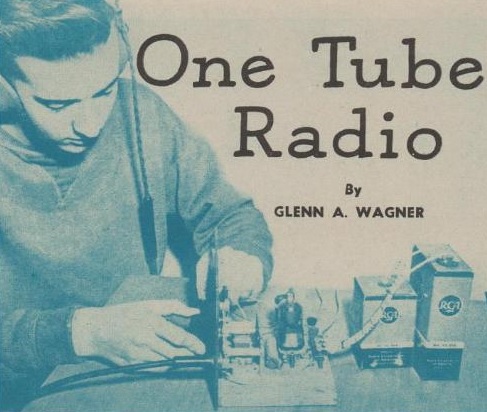
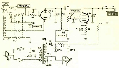
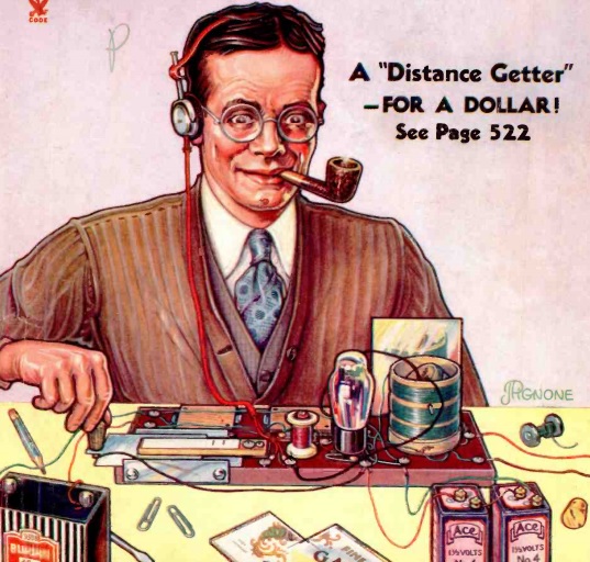
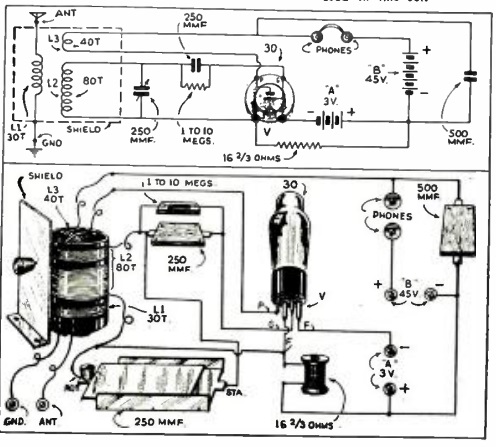
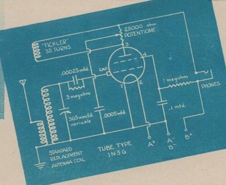 Interestingly, I overlooked this one-tube receiver appearing in the same magazine a few months earlier. In the January 1950 issue of Boys’ Life appeared this one-tube receiver. The article was written by one of the same authors as the September article, Glenn A. Wagner. The January receiver appears to cover the broadcast band, since it calls for a “standard replacement antenna coil” along with a 365 uF variable capacitor. It uses a single 1N5G tube with a 1.5 volt battery for the filament, along with a 45-90 volt B battery. It’s all mounted on a 5×7 pine board.