Category Archives: Radio

Jamboree On The Air 2015

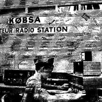
This weekend is Jamboree On The Air (JOTA) and on Saturday, I’ll be with K0BSA at the North Star Museum of Boy Scouting and Girl Scouting in North Saint Paul, Minnesota.  K0BSA is sponsored by the Minnesota Youth Amateur Radio Council (MNYARC), and photos of previous JOTA operations are available on their website.

JOTA is an international scouting event which allows Scouts around the world to communicate via amateur radio with other scouts and other amateur radio operators.  Our event at the North Star Museum is open to all Scouts, and to the public.  It’s free of charge (although we encourage you to also visit the rest of the museum while you’re there, which does have an admission charge.)

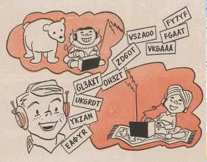
This is the 58th annual JOTA, the first one being run in 1958.  The illustration above is from the announcement for the 1959 version, which at the time was called Radio-Jambo.  The call signs in the illustration were Scout headquarters stations around the world that were on the air that year.

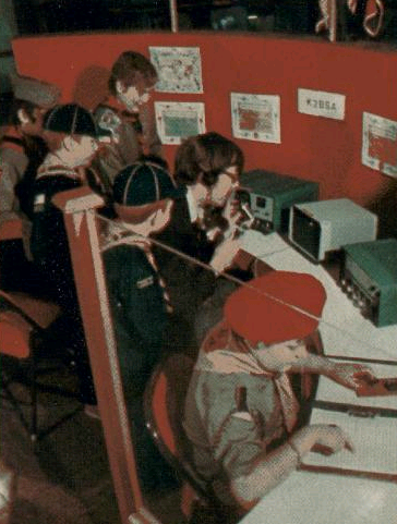
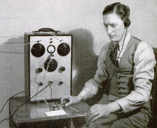
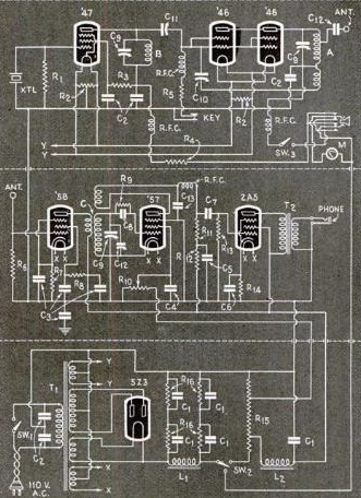
The K0BSA call sign has been connected with the Northern Star Council of the BSA for many years, and I never realized that it had an earlier use.  The 1960 National Scout Jamboree was held in Colorado Springs, Colorado, the only time the event has been held in “Zero Land.”  There has been Radio Scouting at most, if not all, Scout Jamborees, and in 1960, the official station of the Jamboree was assigned the K0BSA call sign.  While the quality of this scan is poor, he Scout shown at the controls of K0BSA in this photo is Steve Wood, K4FJO, of High Point, N.C., who was one of many guest operators of the station.  On his QRZ.com profile, K5KG reports that he was on staff at the Jamboree trading post, and spent all of his off hours at the station.

The June 1960 issue of Boys’ Life reported that K0BSA would be operating on all bands from reveille to taps on both phone and CW, with Pedro clomping at the key or braying into the mike.

If you’re in the Twin Cities and have an interest in radio and/or scouting, please stop by and visit.  The event is open to Cub Scouts, Boy Scouts, Girl Scouts, and Non-Scouts, which should cover just about everyone.  If you’re elsewhere, you can check with your local Scout council.  And, of course, if you’re a Ham, please listen for stations calling CQ JOTA and help introduce a Scout to Amateur Radio.

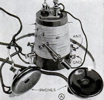
I will also be counseling the Radio Merit Badge.  Last year, about 20 Scouts earned the merit badge.  “Back in the day” when I was a Scout, the merit badge required a knowledge of Morse Code, meaning that the Scouts who earned it usually did so after getting their amateur license.  However, that has changed in recent years, and the merit badge is now more of an introduction to radio.  My goal is to get Scouts interested in Amateur Radio, and a few of them have followed up by getting their license.  I hope I once again have the opportunity to help Scouts who want to follow up and get their “ticket.”


K2BSA in 1975

K2BSA1975Shown here is the flagship Amateur Radio station of the Boy Scouts of America, K2BSA, as it appeared 40 years ago this month, in the August 1975 issue of Boys’ Life.

As reported in the magazine, the station was then located at the Johnston Historical Museum, on the grounds of the BSA’s then national headquarters in North Brunswick, New Jersey. K2BSA is still active, although it no longer has a fixed location from which it operates. It is on the air on multiple bands and modes at BSA Jamborees. At the most recent one in 2013, I was on staff, and thousands of contacts were made around the world. In addition, the station call sign and even portable equipment are available for loan by licensed hams who are scouts and scouters for use at scouting events. In this way, the call sign is frequently heard during Camporees and other events at which scouts get a chance to experience amateur radio.

The article notes that in 1975, the station was put on the air on weekends on a monthly basis to allow visitors to speak to other Scouts around the country.

A larger reincarnation of the museum is open to the public at the National Scouting Museum near the organization’s present headquarters in Irving, Texas.

(Scouts who are working on the Scouting Heritage or Radio merit badges will find helpful information for both at my website.)

Click Here For Today’s Ripley’s Believe It Or Not Cartoon


1945 Kids Radio-Phono Combo

1945PMradiophonoThe young man shown here is presumably the son of Popular Mechanics author Arthur I. Rattray, and is shown next to the radio-phonograph assembled by his father, as described in the July 1945 issue of the magazine.

In the article, he notes that perhaps readers might have a small boy or girl who would like to play records and listen to the radio with a phono-radio combination of their very own. He notes that such units would undoubtedly be plentiful after the war, “but that does not solve the immediate problem.” Therefore, he decided to put one together himself. He did so by combining an old midget radio (probably similar to the $7.95 set featured in an earlier post) with an old table phonograph. He housed them in the legs and braces from a discarded radio console.

He ran the phono cartridge directly to the radio’s audio output tube. He noted that this hookup “does not permit full volume, which is an assset rather than a liability,” but that the volume was sufficient for both radio and phono.

I doubt if anyone is going to recreate this particular project. But one warning is in order. One side of the phono cartridge (and probably the metal tone arm) is connected directly to the radio chasis. Depending on the set, there’s a 50/50 chance that this is hooked directly to the hot side of the AC line cord.

Click Here For Today’s Ripley’s Believe It Or Not Cartoon


1951 Boys’ Life One Tube Receiver

1951BLrcvrThe one-tube shortwave receiver shown here appeared in Boys’ Life magazine in October, 1951. It’s a very simple regenerative circuit using a single 3A4 tube. According to the accompanying article (which carried no byline), the circuit was designed by the ARRL. The filaments were powered by the two dry cells in series, with a 22.5 volt battery supplying the B+. The Boys’ Life editors priced the components at $17.05 in New York, and noted that most Scouts could beat that price both by shopping around and by asking a friendly local ham for components from the junk box.
1951BLrcvrSchematicThe article is a bit sketchy on details; in fact, it doesn’t mention the tuning range. But from the size of the coil and capacitor, I’m guessing that its coverage is in the vicinity of 40 meters. The Novice class license had just been created by the FCC, and the article notes that the little receiver would be good for code practice for earning that license:

For your money and time you will have a working receiver capable of picking up amateur signals, ships at sea, aircraft, and the code-practice broadcasts of the American Radio Relay League. The League broadcasts at 9:30 P.M., Monday through Friday, at Eastern Standard Time. If you’re after the Novice Class ticket, you’ll find the ARRL broadcasts tops for real practice.

The same receiver appeared in the Radio Merit Badge pamphlet, a copy of which has been scanned and placed online by AL7FS.  It appears that the receiver appeared in the merit badge book until 1962. From the text, it appears that a requirement at that time was to construct a receiver and use it to log five stations, and this one would certainly be up to the task.

Click Here For Today’s Ripley’s Believe It Or Not Cartoon


Steam Powered CW Transmitter

SteamPoweredHamTX

QRP’ers wanting to get on the air with a novel power source will appreciate the steam powered transmitter that appeared in Popular Electronics fifty years ago this month, July 1965.

The author, Hartland B. Smith, W8VVD, describes a one-transistor crystal controlled transmitter with a power output of 10-15 milliwatts, powered by a DC motor attached to a model steam engine. The motor (being used as a generator) was on a hinged mount, with a rubber grommet contacting the steam engine flywheel and with a rubber band providing the necessary tension. The rig was tested with 3 volts, but the generator was said to put out up to six volts.

The steam engine manufacturer recommended (as they still do) the use of dry fuel tablets, but the author noted that anything from a candle to a propane tank could be used. To avoid the need for frequent refueling, the author settled on a propane tank, resting between two wooden blocks.

The author notes that almost any of the model engines on the market would be up to the task, but he recommended one with a fairly large boiler to avoid delays caused by needing to refill and build up a new head of steam.

Model steam engines, practically identical to the one shown in the 1965 article, are still available, although they can be a bit pricey. My son owns a Jensen Model 75, although I don’t think we paid anywhere near its current price on Amazon. The Wilesco Model D5 appears comaprable, at a more reasonable price. Either should put out more than adequate power to run a small transmitter similar to the one shown in the article. The tank does appear somewhat smaller than the one in the article, but will give several minutes of run time, enough for a short QSO, if not a long ragchew. We power ours with the Esbit Dry Fuel Tablets, although it could easily be run with alcohol. Because of the smaller tank, it would probably be tricky to rig it up to run from the propane tank, although that could probably be managed.

The author Hartland Smith was first licensed in 1941, and is still licensed as W8QX.  In addition to writing, he worked as a broadcast engineer, designer, and kit manufacturer.  He has a number of interesting websites which he has linked at this one.  I received a nice e-mail from him, in which he mentioned that had written a number of other articles for “PopTronics.”  I did a search and located quite a few, including the “Camper’s Special” from 1965 and the “Camper’s Cuzzin” from 1967.  Together, they formed an 80 meter QRP station suitable for camping or emergency backup.  The “Camper’s Special” was a crystal-controlled transmitter that put out 5 watts.  The author points out (as many of us later discovered with the modern rediscovery of QRP) that this is just two S-units weaker than a 100 watt signal.  The “Camper’s Cuzzin” was a companion receive converter, which allowed the builder to tune the 80 meter band on a standard broadcast receiver.  It contained three transistors, a local oscillator tuning 5.1 – 5.6 MHz, an amplifier-mixer, and a BFO set to 1.6 MHz.  By setting the converter next to a portable AM radio tuned to 1600, the result was that 80 meter CW or SSB could be heard.

He also designed two transmitters for the novice.  The “Hart-25” from 1955 put out 25 watts, and the “Hart-65” in 1967 put out 65 watts on 80 and 40.

For those looking for an even more challenging QRP transmitter, check out AA1TJ’s voice powered “CW” transmitter described at this link and seen in action on this video.  He worked a QSO of a hundred miles with no power source other than his own voice into a PM speaker.  It was probably quite a bit more than two S-units below a 100 watt signal, but by shouting loud enough, he made QSO’s without any power source, steam or otherwise.

Click Here For Today’s Ripley’s Believe It Or Not Cartoon


1940 “Mighty Midget” One Tube Shortwave Receiver

1940JulyPMrxSeventy five years ago, the father and daughter shown here were putting together a one-tube shortwave receiver according to plans in the July 1940 issue of Popular Mechanics.

The set, the “Mighty Midget” One Tuber, employed a single 1D8-GT, a dual tube, with one half being used as the regenerative detector and the other half serving as an audio amplifier.

Thanks to the efficiency of the multi-unit tube, the set was said to run rings around two-tube receivers of even a year earlier.  “Twenty-meter phone stations roll in with headphone volume at times actually uncomfortable, and there is plenty of ‘sock’ even on weak foreign stations.”

For information on sourcing parts, especially the plug-in coils, see my recent post about a similar two-tube set.

1940JulyPMpic


1940JulyPMschematic

Click Here For Today’s Ripley’s Believe It Or Not Cartoon


1935 Popular Science 80 Meter Portable Station

1935PS80meterstationEighty years ago, Popular Science, June 1935, carried the plans for this complete 80 meter CW station. It could be used permanently in the shack, or as a portable station. The entire station weighed in at about 35 pounds, and could be transported relatively easily. The front panel measured just 18 by 12 inches.

The top third is the transmitter, which uses a type 47 tube as crystal oscillator, and two type 46 tubes as the final amplifier, putting out about 30 watts.

1935PS80meterstationSchematicThe receiver used one type 58 tube as an untuned RF amplifier, with a type 57 tube as regenerative detector. A type 2A5 was used as an audio amplifier.

The bottom section contained the 110 volt power supply, with a transformer supplying 450 volts either side of the center tap. This was rectified by a 5Z3 tube, with several capacitors and chokes doing the filtering. The article noted that where commercial power was not available, the set could be adapted to a vibrator power supply to run off six volts.

1935PS80meterstationFrontPanel

Click Here For Today’s Ripley’s Believe It Or Not Cartoon


Foxhole Radio Update


Gould's rendition of the foxhole radio.

Gould’s rendition of the foxhole radio.

A few months ago, we posted about the history of the “foxhole radio,” a crystal set made with a razor blade detector,  As reported in the New York Times in June 1944 and Time Magazine in July, soldiers at the beachhead in Anzio made these receivers to pass the time. The receiver was later popularized in Jack Gould’s book All About Radio and Television.

Among those to see the plans was Radio Craft editor Hugo Gernsback.  In the September issue of Radio Craft, he pointed out that the original Razor Blade Radio Detector had actually been published by him, in the January 1909 issue of Modern Electrics. He also shows two other similar detectors published in 1906.

The 1909 razor blade detector actually differed from the “foxhole” version, however. The Modern Electrics detector uses two razor blades with a pencil lead balanced on top. The razor blade seems to be serving the function of “cat’s whisker,” as opposed to being the crystal in the foxhole version.

GernsbackRazorBlade


Click Here For Today’s Ripley’s Believe It Or Not Cartoon


1940 Two Tube Shortwave Receiver

1940PS2tubeThis cute little two-tube broadcast/short wave receiver appeared in Popular Science 75 years ago this month in the June 1940 issue.

1940PlugInCoilsIt used  ready-made coils which plugged into the top of the set to change bands. Back in the day, you could buy the coils pre-wound, such as the ones shown here in the 1940 Allied catalog. A set of four coils covering 17-270 meters would cost $1.80. If you wanted to get the bottom of the broadcast band, the coil covering 250-650 meters would be an additional 75 cents.  Plug-in coils are unobtanium these days, but AA8V has a good description of how to make your own forms from a defunct tube and section of PVC.

A 1N5 tube was used as the regenerative detector, with a 1A5 serving as an audio amplifier to drive a built-in speaker. It was powered by a 1.5 volt battery for the filaments, with a 90 volt B battery, also tapped at 22.5 volts.

The builder of this set probably heard a lot of interesting signals on the shortwave bands during the war.

The 1N5 and 1A5 tubes are available at Antique Electronic Supply.  All other parts are readily obtainable, other than the plug-in coils, which you can wind yourself. For ideas on where to find parts, visit my crystal set parts page or my how to stock your junk box page.

1940PS2tubeSchematic

Click Here For Today’s Ripley’s Believe It Or Not Cartoon


Two 1945 Crystal Sets

1945PMXtalSet1Seventy years ago this month, the June 1945 issue of Popular Mechanics carried the plans for the two crystal sets shown here. As the article points out, crystal sets can come in two varieties. The simplest set has little selectivity, and is suitable only for tuning in the one strongest station in a given area. For more variety, a more complex set with more selectivity is required. The magazine showed two sets, one in each category.

The simple set had its coil and all of the other parts mounted on a plastic drinking cup. The more selective set contained two variable condensers, both salvaged from old broadcast radios. Complete crystal detectors could be purchased for about 25 cents, or the builder could make one with a piece of galena. Thus, even with wartime parts shortages, most hobbyists would be able to scavenge together the needed parts.1945PMXtalSet2

For those wishing to replicate one of these designs today, I have ideas for finding parts on my crystal set parts page.

Click Here For Today’s Ripley’s Believe It Or Not Cartoon