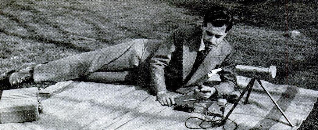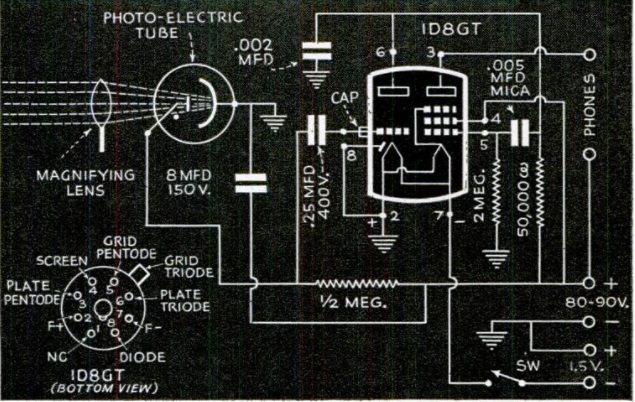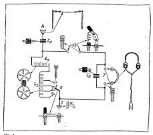
Category Archives: Radio history

1921 Creed Automatic Radiotelegraphy System

No. 7W/3 Reperforator, manufactured by Creed and Company Limited, Croydon, London, England, 1925

Creed No. 7W/3 Reperforator (1925). Image courtesy of Science Museum Group Collection, © The Board of Trustees of the Science Museum, U.K. released under a Creative Commons Attribution-NonCommercial-ShareAlike 4.0 Licence.

No. I.T. Morse Tape Printer (1925).

No. I.T. Morse Tape Printer (1925). Image courtesy of Science Museum Group Collection, © The Board of Trustees of the Science Museum, U.K., released under a Creative Commons Attribution-NonCommercial-ShareAlike 4.0 Licence.

The two devices shown above represent a hundred year old method of automatically decoding International Morse Code. They, along with the sending device, are described in the March 1921 issue of Radio News.

1921MarRadioNews3At the sending end, the message is typed on a typewriter-like keyboard and punched onto a paper tape. An example of the tape is shown below. It’s not immediately obvious that the tape contains Morse code, but upon closer observation, it is. A “dot” is indicated by one hole directly above another hole. A “dash” is indicated by two holes that are slanted. Once you see this, the Morse code is obvious. The first word shown here is “the.” The first two holes are slanted. This is a single dash for the letter T. This is followed by four sets of holes, one directly above the other–four dots, for the letter H. Next, there is a single set of vertical holes, another dot for the letter E.

Once this tape is produced, it is sent through another machine which keys the transmitter and sends the Morse signal over the air.

At the receiving station, the two machines shown above are used to receive and print the message. The reperforator (top) connects to the receiver and produces an exact duplicate of the paper tape. Then, the paper tape is fed into the Morse Tape Printer, which prints the message on a paper tape.

The process was known as the Creed Automatic System, named after inventor Frederick G. Creed, an important figure in the development of the teleprinter. At the beginning of the 20th Century, Creed was told my none less than Lord Kelvin  that “there is no future in that idea.” Undaunted, he managed to sell twelve machines to the British post office in 1902.  The 1921 machine described for use with wireless telegraphy appears to be a variation of that device.

By the late 1920s, the company was producing teleprinter equipment using a variant of the five-bit Baudot code.  The company became part of IT&T, and Creed retired from the company in 1930. Among his later projects was the “Seadrome,” a floating airport which could be placed along international air routes. The project is described in a March 1939 article in the Glascow Herald, and was undoubtedly a casualty of both the War and increased aircraft range. The Seadrome is the subject of US Patent 2238974, applied for in February 1939 and granted in April 1941.

The images above are copyrighted and provided courtesy of the Science Museum Group, U.K., where they are on display, and released under a Creative Commons Attribution-NonCommercial-ShareAlike 4.0 Licence.

Santa Catalina Radiotelephone, 1921

1921MarRadioNews1A hundred years ago, if you were located 26 miles across the sea (40 kilometers, for those in leaky old boats) at Avalon, Santa Catalina Island, California, you could enjoy the luxury of telephone service with any telephone in the United States, thanks to the radiotelephone service operated by Pacific Telefone and Telegraph Co., as described in the March 1921 issue of Radio News.

The system consisted of stations KUVX at Avalon and KUXT at Long Beach. A complicating factor was the presence of naval station NZL, also located at Avalon. To avoid interference, the radiotelephone receiving station employed a wave trap to null out NZL’s frequency. The article gives the radiotelephone wavelength of 425 meters (706 kHz). The system was full duplex, meaning that there would be different transmitting and receiving frequencies. Since the 425 meter wavelength is discussed in conjunction with the wave trap on the receiving antenna, it appears that the Long Beach station transmitted on 425 meters, and Avalon transmitted on a different frequency.

The author described an interesting catch for an SWL as part of a test conducted by the Avalon station. He listened in on a conversation from Avalon to the mainland, which was carried by the transcontinental telephone lines to New York, where the call was carried by another radiotelephone station to a ship in the Atlantic. The author reported that the voice was a little distorted, but could be clearly heard throughout the ten minute test.

The Avalon station was powered by a motor generator, and to avoid having to restart the power, the carrier was left on 14 hours a day, with calls to and from local hotels, stores, and residents carried as needed. A licensed radio operator oversaw the transmitter, connected to an eight-wire antenna, and receiver, connected to a loop antenna. A telephone operator put through the calls, presumably with another operator at the Long Beach side of the circuit doing the same.

The system was able to transmit telegraph signals simultaneously with telephone conversations without interference. This was accomplished by “superimposing a high pitched harmonic on the carrier wave.”

A more detailed technical description of the system can be found in the December 1921 Proceedings of the IEEE.  You can also find additional references at Wikipedia, which notes that the system was replaced by a submarine cable in 1923, ending the possibility of radio listeners being able to tune in to telephone conversations.

1921MarRadioNews2


Radio Hams Practice for War: 1941

1941MarPM
In 1941, the ham radio operator shown here was asked how long he would need to get his portable station into operation in the field. “Six minutes is the average time,” he replied. The officers asking the question were skeptical, but they watched as he opened his suitcase, hooked up a car battery, hammered in a ground stake and slung the antenna into a tree. He then tapped out a message to the control station fifteen miles away.

This was but one of the tales recounted eighty years ago this month, in the March 1941 issue of Popular Mechanics, in an article entitled “Radio Hams Practice for War.” It detailed the work of the 1800 member Army Amateur Radio System and pointed out that in time of war, thousands of trained hams would go into the military for active duty, and others would take on civilian duties such as listening for clandestine stations.

In another exercise, hams were asked, “your radio transmitter is completely smashed by a falling chimney. How long will it take to borrow an old broadcast receiver from a neighbor and build a new transmitter from its parts?” Another ham was ordered, “simulate destruction of your main transmitter. Rig up your emergency equipment and report back on the air as soon as you can.”

The article detailed a number of ways in which hams were “preparing themselves against a possible ‘M’ day.”


Record Storage Woes: 1941

1941FebRadioRetailing2This young woman is obviously distraught and overwhelmed, but it’s not her fault. It’s the fault of her radio-phono dealer, who neglected to sell her anything in which to store her records. She is pictured in the February 1941 issue of Radio Retailing, which reminds dealers of the potential peril, and explains that “people who buy soon have scarred and battered records scattered all over the house unless dealers simultaneously sell accessories to keep them in.”

To prevent this from happening, the magazine listed the manufacturers of a number of different racks and cabinets, any of which would have solved this woman’s problems. The next page of the magazine showed one reason why the problem was becoming acute: It was the prevalence of compact combination radio-phonos hitting the market. The player didn’t take up much space, but the records that it played represented a storage problem.1941FebRadioRetailing3


1971 EBS False Alarm

MushroomCloudFifty years ago today, the Emergency Broadcast System (EBS) sent out a warning that the nation was under attack. Thankfully, it turns out it wasn’t. A test was scheduled for that Saturday morning, but an operator at the Cheyenne Mountain complex put in the wrong tape. Instead of the tape announcing that it was only a test, he ran the tape for a real attack. It contained the code word “hatefulness” to authenticate the message.

At radio stations around the country, DJ’s ripped open the envelope next to the teletype machine containing the authenticating code. And sure enough, that was the correct code word for that day. Stations were supposed to cease normal operations and begin broadcasting information about the attack. But that information was never forthcoming.

Since a test had been scheduled, many stations suspected that there was an error, but it wasn’t confirmed officially for 40 minutes. The most famous recording from that day comes from WOWO in Ft. Wayne, Indiana, which you can hear in this video, where announcer Bob Sievers interrupted the Partridge Family with the news:

You can also listen to the event from WCCO Minneapolis at RadioTapes.com.


1961 Emergency Call Box

1961FebEI3Sixty years ago, the February 1961 issue of Electronics Illustrated showed this prototype of a highway emergency call box from Hoffman Electronics, dubbed the “safety satellite.”

The unit is self-explanatory. In an emergency, the motorist would push the appropriate button for police, fire, ambulance, or service, which would be dispatched from a central control point.

While the FCC had not yet assigned a frequency, the prototype three-tube VHF transmitterwas operating on 72-76 MHz, using FSK transmission with about 1 watt transmitter power. While the article does not specify, from the photo of the device, it appears that the message is sent by a motor-driven keyer.

It was said to have a line-of-sight range of about 25 miles. Each emergency message would transmit for 1.5 seconds, and would represent about 5 minutes charging time with the silicon solar panels. Six NiCd cells were used. On transmit, one was used to power the filaments, and the other five went to a solid-state power supply to provide the B+ voltage.

The price tag for each transmitter was about $300, with the FM receiver running an additional $250-275. Depending on the complexity of the decoding and display consoles, the monitor station could run a total of $3000.

The system was touted as a bargain, since the cost to wire a highway would be about $3000 per mile, with one transmitter every quarter mile on each side of a freeway. This compared to about $8000 per mile to install emergency telephones. When charging, the batteries would be in parallel.

In addition to emergency highway use, the system was capable of sending telemetry for industrial applications.


1941 Minnesota Radio Stations

1941FebServiceAs we’ve previously written, on March 29, 1941, most broadcasting stations in the United States changed frequency, as the top of the dial moved from 1500 kHz to 1600.  This listing shows all stations in Minnesota at that time.  The first column shows their old frequency, and the last column shows the new frequency, many of which still look familiar today.

The listing appeared in the February 1941 issue of Service magazine.


St. Paul, MN, City Radio System, 1951

1951FebFMTV

St. Paul Police Sgt. Hans Peterson.

Shown above, 70 years ago, is Sgt. Hans Peterson of the St. Paul, MN, Police Department, at the console of the city’s mobile radio system. The system was described in detail in a two-part series appearing in the February and March, 1951, issues of FM-TV-Radio Communications magazine, authored by the city’s Commissioner of Public Safety, Robert F. Peterson.

Peterson notes that, as in most other cities, greatly increased demands had been placed upon the police department since the war, due to added services, as well as additional crime and juvenile delinquency. And with the development of long-range aircraft, the city found itself closer to Russia than the cities on the east coast, making civil defense a concern. “Obviously, more manpower is indicated, but in St. Paul our 40-hour week and limited budget make any substantial increase in personnel out of the question.” Therefore, the city turned to technology, in the form of a modern radio system, to increase efficiency of officers. The system also handled traffic for the city of West St. Paul and the Ramsey County Sheriff’s Department.

Morrison caption.

Engineer Bob Morrison standing beside police cruiser. Selective call light is visible above center of windshield.

The system consisted of equipping 53 police vehicles, as well as fire stations and vehicles, with dual-frequency radios with selective calling capability. All outgoing calls were handled on 159.09 MHz from a console at the Public Safety Building. A leased telephone line led to the transmitter and receiver atop the First National Bank Building. The transmitter room was, understandably, kept locked at all times, and also had a CO2 fire suppression system installed. The door and fire system had monitors that were linked back to the main control point, so that the dispatcher would be aware of any intrusion or fire.

Normally, all units operated on 159.09 MHz. But the mobile units were all equipped to transmit on a secondary frequency of 158.97 MHz, which was continually monitored by the dispatcher. This allowed mobile units to make emergency calls even during longer broadcasts from the dispatcher.

A key element of the system was the selective calling ability. The console shown above was equipped with dozens of switches, one for each mobile unit. One of these could be switched on to selectively call any car. Normally, officers in the squad would be listening to the radio at all times. But previously, if they had to get out of the car to perform their duties, they were out of service for further calls. For example, if an officer were out of his squad car investigating a traffic accident and a robbery occurred just around the corner, there would be no way to alert the officer.

Selective calling provided a solution. When an officer was out of his car, he could still be alerted by a light mounted above the windshield, or perhaps a horn. These were connected the the selective calling system. If the officer was needed, the dispatcher would flip the switch, the light would come on, and the officer would know there was a priority call.

A duplicate console was connected. Shown below, radio operator Art Tweet is shown at this console. The radio operator was responsible for system operation, but in rush hours, he could assist the dispatcher.

Radio Operator Art Tweet

Radio Operator Art Tweet

Tierney caption.

Police Chief Charles J. Tierney.

Mattocks Caption.

Fire Chief William H. Mattocks.

Peterson Caption.

Commissioner of Public Safety Robert F. Peterson.

Ginther Caption.

Superintendent of Radio L.A. Ginther.


1946 Personal Receiver

1946FebPS2This gentleman has found marital bliss, thanks to a personal radio receiver he put together according to the plans in the February 1946 issue of Popular Science.

As the magazine pointed out, “instead of thinking harsh thoughts about members of your family who frown on your radio listening when they want to read or sleep, try one of these compact personal radios that make the entertainment of the airwaves your private business.” The wife is undoubtedly in that category, but he made the radio his private business by listening with headphones while she slumbers in peace. Presumably, there were harsh thoughts prior to making this set, and it probably saved the marriage.

The circuit is a three-tube regenerative set. One tube serves as a rectifier to supply the B+ voltage in the AC-DC “hot chassis” design. To run the filaments, multiple “curtain burner” line cords, adding up to 600 ohms are used. While the set is designed for headphones, it’s powerful enough to drive a speaker, and the optional hookup for a speaker is shown.

1946FebPS3