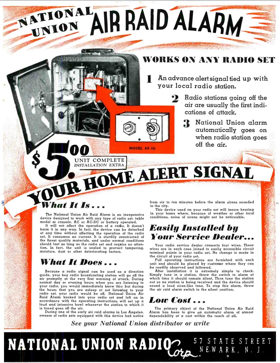
 Eighty years ago this month, the April 1942 issue of Service magazine carried this ad for the Model AR-101 Air Raid Alarm from National Union Radio Corp., 57 State Street, Newark, NJ.
For $5 plus installation, the small device was attached to “any type of radio set,” although I suspect the radio in question had to be a superheterodyne with AVC. But since most five-tube radios of the time fit that description, it was pretty close to “any type of radio set.”
During an air raid, radio stations would go off the air, so as not to serve as a beacon for incoming aircraft. According to the ad, the stations going off the air “are usually the first indications of attack.” The ad noted that during the early air raid alarms in Los Angeles, owners of radios with this device would have received warning six to ten minutes before the sirens sounded. And inside the house, the sirens might not be noticeable.
When the station went off the air, the radio equipped with this alarm would emit a “loud siren-like tone.”
According to the ad, the alarm was “sturdily constructed of the finest quality materials, and under normal conditions should last as long as the radio set and require no attention. In fact, the unit is sealed to prevent tampering, moisture, dust, or other deteriorating factors.”
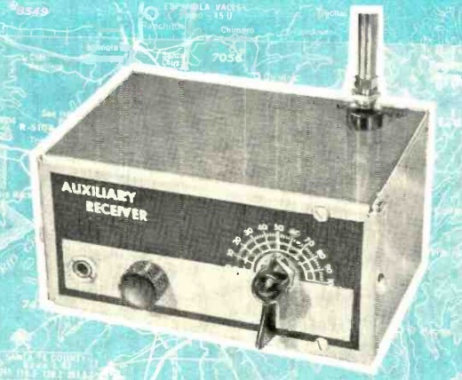
And I suspect it was sealed for another reason–to conceal just how simple the circuit was, especially given the $5 price tag. The image in the ad shows a tiny box, with only a switch and what appears to be a potentiometer. The device had four wires that connected to easily accessible points in the radio.
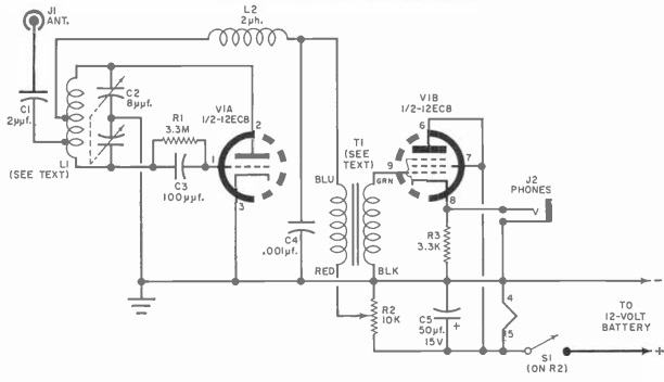
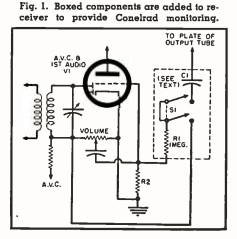 I haven’t been able to find any more information about this device, but I suspect it’s very similar or identical to the 1957 “CONELRAD The Easy Way” circuit we featured previously. In that circuit, shown here, when the radio is set into the alarm mode, the AVC voltage is used to bias the first audio tube to cut-off, rendering the radio silent. But if the station goes off the air, the AVC voltage is zero, and the first audio stage comes back to life. The output from the final audio amplifier is fed back through the capacitor, resulting in feedback, or what the ad would call a “loud siren-like tone.”
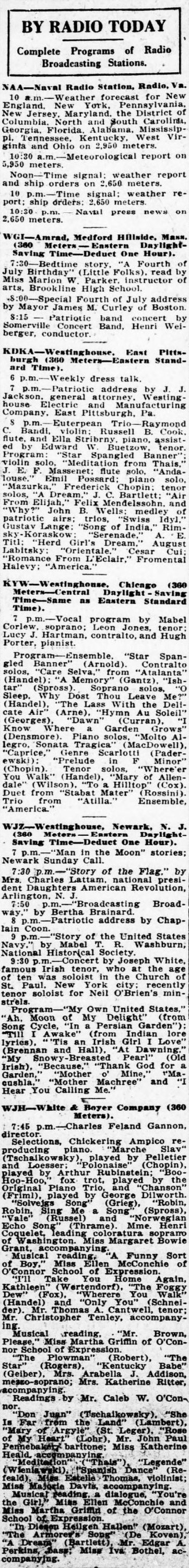 If you were the owner of a radio a hundred years ago, here’s an idea of what you would have been able to tune in, as listed in the Washington Evening Star, July 4, 1922.