Category Archives: Radio history

SWL’ing Missile Launches and Nuclear Blasts

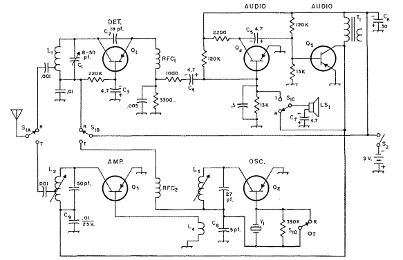
Screenshot 2023-01-24 12.58.51 PMSixty years ago this month, the British Radio Constructor carried the plans for this interesting project, suitable for monitoring missile launches. Or, if you were lucky and happened to be tuned in at the right time, you could hear the signature RF signals of a nuclear blast going off!

The project itself was quite simple.  It consisted of a loop antenna, feeding to a one-transistor ELF detector and one stage of audio amplification.

Screenshot 2023-01-24 12.59.40 PM


1923 Radio at Home and On The Farm

1923JanWirelessAge1A hundred years ago, radio was rapidly becoming a familiar part of the home, whether it was in the city or on the farm. The cover of the January 1923 issue of Wireless Age, above, shows an idyllic scene of radio by the hearth.

1923JanWirelessAge2But radio was more than just a pastime for the urban upper class.  It was rapidly making it’s way to the farm, and it was bringing rural people closer to the city.  The magazine contained a feature describing how radio was rapidly becoming a necessity on the farm.  Farmers could receive up-to-the-minute market reports, and the main complaint from farmers was that they were being read too fast to write down.  And weather warnings could make a huge difference in the safety and profitability of farm life.  But in addition to the purely practical, radio was changing rural life by allowing residents to hear news, concerts, and lectures.  Shown here are Mrs. Albertina Schockweiler, her daughter and grandson, as the pull in a program on their farm in Osseo, Minnesota.


Oakford Music Co., Omaha, 1923

Screenshot 2023-01-25 12.33.39 PMA hundred years ago today, the January 27, 1923, issue of the Omaha Bee carried this ad for the Oakford Music Co., 419 S. 16th, Omaha.  The store announced that it was branching out into the radio business in a big way, complete with a special radio room.  The new department was to be headed by radio expert and former aviator Lt. L.E. Stewart.


1948 QRP Transmitter

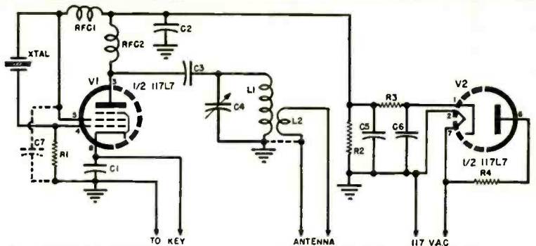
Screenshot 2023-01-24 9.17.10 AMScreenshot 2023-01-24 9.26.41 AMSeventy-five years ago this month, the January 1948 issue of QST showed this one-tube one-watt transmitter using a 1S4 tube.  A flashlight battery supplied the filament voltage, and 30-90 volts of B+ was required.  Coil data was shown for 80 meters, but the circuit could easily be used on other bands.

A balanced antenna could be connected to L2, or that coil could be dispensed with and the antenna connected to the point marked X, worked against ground.  From Connecticut, the set made 22 contacts with 10 states over the course of 10 hours.  It was sent to the magazine by Ernest Lindsey, W4BIW.


1973 ZN414 Receiver

Screenshot 2023-01-12 12.19.59 PMFifty years ago, this British woman probably had the smallest radio receiver on her block, and she constructed it herself, thanks to the plans contained in the January 1973 issue of Popular Wireless. The set owed it’s diminutive size to then-revolutionary ZN414 integrated circuit, manufactured by Ferranti, which contained all of the circuitry for a tuned radio frequency (TRF) AM receiver onto a single chip. The chip’s specs covered long wave up to about 5 MHz, but in a prototype made by the magazine, the chip was able to cover the 49 meter shortwave band. The version shown in the magazine covered the medium wave band, but could be easily moved to different frequency ranges. For strong stations, the set sometimes tuned broadly, but when two stations were close together, it would separate them, even if one was strong.

The small set had good sensitivity, and tuned in Radio Luxembourg loud and clear. Audio was through a crystal earphone. The case for the radio was a snuff container, which the author reported could be purchased for 9 pence (including the snuff). The author added that “if you haven’t tried snuff, this is your chance,” and that he was partial to the occasional pinch.

The ZN414, like most things, is available on eBay. But it’s replacement, the TA7642, is readily available for those seeking to duplicate this project.

Screenshot 2023-01-12 12.21.52 PM

Unwinding Twisted Pair: 1948

1948JanPracWir2
Seventy-five years ago this month, the January 1948 issue of the British Practical Wireless showed this self-explanatory tip for unwinding twisted pair.

The idea was sent into the magazine by one R.L.G. of Chelmsford, who pointed out that it was often necessary to unwind a long length of “lighting flex,” which was apparently in common use in Britain for home lighting circuits. But he points out that any amateur who has attempted this learns that it becomes tedious after a few feet. With the device shown here, it was an easy matter. You just pull the wire taut, and start twisting (usually clockwise). In just a few minutes, the wires will separate. It is necessary to move back slowly, as the wires get longer when unraveled.


Some links on this site are affiliate links, meaning that this site earns a small commission if you make a purchasing after following the link.

WWV, 1953

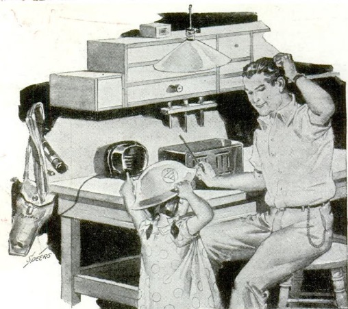
1953JanBLSeventy years ago this month, the January 1953 issue of Boys’ Life carried this illustration showing some of the uses to which the signal of WWV could be put.

The railroad and the factory worker were on time thanks to the time broadcasts. The time was announced every five minutes, in both Morse code and voice. The Morse was in GMT, and the voice was Eastern Standard Time. The musician took advantage of the standard 440 Hz tones, which were the A above Middle C.

The code key represents an idea shown by the magazine. For an easy code practice set, you could put the key in line with a pair of headphones and tune into WWV. Then, you could key the tone on and off.

In addition, the station sent radio propagation disturbance warnings, with the Morse W, U, or N. W meant warning, U meant unstable, and N meant normal.


1963 Stealth Antennas

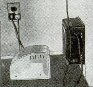
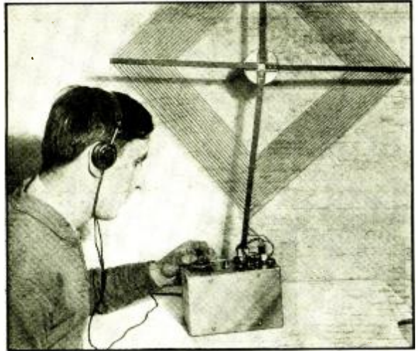
1963JanEIIt’s become a more common issue these days, but even 60 years ago, some hams and SWL’s were faced with the issue of needing to put up an antenna where they weren’t allowed. As highlighted by this article in the January 1963 issue of Electronics Illustrated, one solution, then and now, is to use an invisible antenna. The easiest way to do that, as apparently done by the owner of the antenna shown above, is to use a very thin gauge wire. The article suggested 18 gauge or smaller (larger numbers being smaller). The best choice is often enamel wire, and it is sometimes possible to select a color that matches the background, for added stealth.

I’ve discovered that one source of very cheap almost invisible wire is cheap speaker wire.  Remember, when you see the price per foot, you’re actually only paying half that much, since you can unzip the wire before using it.  And it often comes with clear insulation, meaning that it’s almost invisible from even a short distance away.

The magazine suggested a type of insulator to use, but modern hams have discovered that the insulator is often unnecessary. Instead, just tie the end of the wire to a piece of monofilament fishing line, which is even less visible.

The article also suggested the possibility of becoming patriotic and installing a flagpole on your house. Especially for higher frequencies, they can form the basis for an excellent antenna system.


Some links on this site are affiliate links, meaning that this site earns a small commission if you make a purchase after using the link.

Electronic Measurements Quiz

1963JanPE4

Today’s quiz is from 60 years ago, the January 1963 issue of Popular Electronics. But the vast majority of the information is still good. The answers appear tomorrow.  How well do you know your VOM?