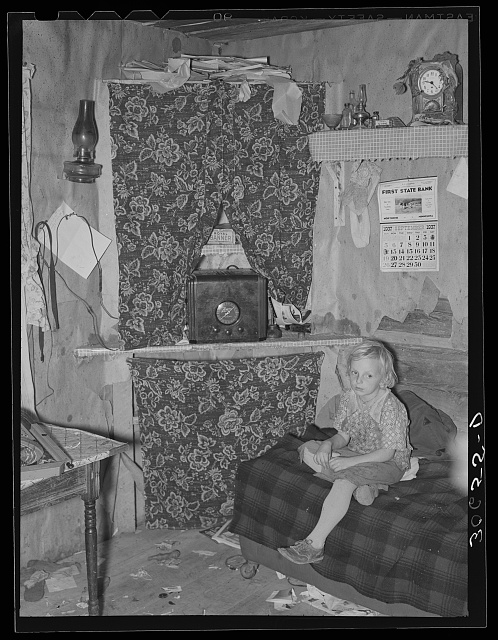
 This young woman is now close to 90 years old, but she is shown here, according to the calendar on the wall, in September 1937, in her living room in a farm house near Northome, in Koochiching County in far northern Minnesota. The house looks humble, and I’m not sure exactly what’s going on there in the corner. They don’t have electricity, as evidence by the kerosene lamps, but they do have a radio, and it’s a rather impressive radio.
The radio is a Zenith model 4-B-132. You can see a beautifully preserved example at the Radio Attic Archives. (In fact, if you want to buy that radio, it’s for sale at the Radio Attic.) Most farm sets used two batteries–a low-voltage battery to run the filaments, and a B battery of something like 90 volts. But with this set, Zenith used a different tactic, which probably saved the owner a lot of money over the years. It used a single 6-volt battery, and, like a car radio, it included a vibrator power supply to generate the B+. When the battery got low, it could be recharged with the car or tractor.
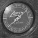 Now that we know what the radio is, we want to know what they were listening to. And if we do a close-up of the dial, we can see that it’s tuned between 1400 and 1500 kHz. That makes it easy. The only logical suspect is KSTP, which was then (prior to the NARBA switch, when they moved to 1500) on 1460 kHz, with 25,000 watts day and 10,000 watts night. At 206 miles away, the station would come in loud and clear at night, and probably during most of the day as well. It was a good receiver, there was little in the way of electrical interference, and there were few other stations close to it on the dial. In fact, a 1937 promotional brochure from the station claims the county’s 2400 radio homes (out of a total of 3345 families) as being part of the station’s secondary service area, along with counties in Wisconsin, Iowa, and the Dakotas.
The photo was taken by Farm Security Administration photographer Russell Lee, and is available at the Library of Congress website. Another picture featuring the family and the radio can be found at this link.
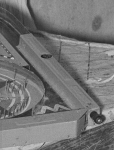 Some people look at a picture like this one and feel sorry. There was a depression going on, and there’s a reason why there aren’t a lot of farms these days in Koochiching County. Life was undoubtedly tough. But despite their otherwise austere living conditions, they owned a $40 radio ($854 in 2023 dollars) which undoubtedly brought much pleasure during the long winter nights. And by zooming in on the left side of the picture, we see that this girl, along with her brother and sister, also owned this pinball machine. We suspect this girl had a happy childhood, and a happy life.
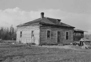
Unfortunately, while many of these old Farm Security Administration photos include a caption with the names of the people, this one does not. All we know is that this family lived on a farm near Northome, probably in the house shown below, which was the next negative on the roll.
It’s a longshot, but if you know the people in the picture, or you are a member of this family, we would love to hear from you at clem.law@usa.net.
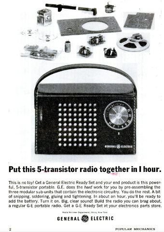 Sixty years ago, if you were in the market for a transistor radio, and you had a little bit of mechanical aptitude, you couldn’t really go wrong getting this kit from General Electric. It was a kit, but the hard work, namely the construction of the individual circuit boards, had already been done at the factory. You just had to snip a few wires, and do a little bit of soldering, assembling, and gluing. In less than an hour, you would have a good five-transistor radio.
